Traditionally, the objective of monitoring is verification of the tunnel design. Key physical parameters are measured and compared with predicted values. In case of significant deviations, an adjustment of the tunnel design may be indicated.
Beyond this, geotechnical instrumentation may also be used in the quality assessment of certain tunnel construction procedures. In critical situations (e.g. tunnelling beneath settlement-sensitive structures in inner-city areas) it can yield construction control signals for the entire tunnelling operation.
This first article looks at recent European developments and practices in performance monitoring for tunnel design purposes. Part two, to be published next month, focuses on geotechnical instrumentation to assist with construction control.
Introduction
In underground construction, geotechnical instrumentation is used for purposes which are summarised in Table 1.
For evaluation of the tunnel design, a set of elementary tunnelling instrumentation is commonly employed.
The discussion of the instrumentation (together with some selected additional instrumentation) will be in accordance with the common engineering purpose which can be classified as follows:
– instrumentation for an empirical proof of a new equilibrium after tunnel excavation: convergence and/or geodetic deformation monitoring;
– instrumentation for the monitoring of displacements and stresses to compare measured and predicted values for evaluation and improvement of the tunnel design.
Surveying methods
Convergence measurements and monitoring of the displacements of the excavated tunnel surface by surveying methods are part of the routine operations in today’s tunnel construction.
In essence, the change of the displacements is monitored and correlated with tunnel construction procedures such as excavation, installation of the ground support and closure of the invert. ‘Stabilisation of the entire system and its safety, the necessity of additional support and, in reverse, the permissibility of reducing the support system is judged on the basis of convergence or displacement measurements at, or near, the excavated tunnel surface’. (Leopold Müller, 1978; p 607).
For convergence measurements, the distance between two points on the excavated tunnel surface is measured by specially manufactured tapes (so-called ‘convergence tapes’ or ‘tape extensometers’).
A common technical feature of such tapes is the high reproducibility of their tensioning force in a measuring position. The measuring points are defined by convergence bolts which are attached to the linings, e.g. placed in the shotcrete in a manner that their measuring heads are pointing towards the excavation and remain accessible throughout the lifetime of the monitoring project.
After installation of the bolts, a first round of reference (or ‘zero’) convergence measurements is carried out. By way of follow-up measurements (and subtraction of the measured values from the respective values of the zero measurement) the change of the distance between the bolts can be determined.
The accuracy of convergence measurements is in the range of ±0.003 to ±0.1mm and depends on a number of factors, among them the type of instrument, the material of the tape and the type of coupling of the tape to the bolts (see table 2).
Note that convergence measurements are generally more accurate than geodetic displacement measurements (see table 2).
In today’s European tunnelling practice, convergence tapes are hardly used anymore. Instead, geodetic monitoring is quasi-standard and has substituted tape measurements almost entirely. This is despite the lower system accuracy of the geodetic method.
Only in special or sensitive projects (e.g. underground research laboratories, nuclear repositories) are convergence tapes still in use. Generally in these applications, tapes of the Accuracy Class I or II (see table 2) are employed.
The main reason for the substitution of convergence tape measurements by geodetic deformation monitoring is associated with the following principal disadvantages of convergence tape measurements:
– high degree of interference with tunnelling operations;
– no realistic perspectives for automation;
– restricted to relative displacement measurements.
Geodetic deformation monitoring
In European tunnelling practice today, geodetic monitoring represents the real backbone of tunnel performance monitoring in terms of volume of work and turnover figures.
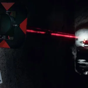
As indicated in fig 1, displacement measuring sections are routinely installed every 10 to 25 m along the tunnel axis. Commonly, each section consists of five reflector targets (fig 2) which are equally spaced along the tunnel periphery. This set-up is modified in partial tunnel excavations (fig 3). The targets are surveyed, up to a distance of maximally 100m, by precision total stations with automatic data acquisition. Each set of readings consists of two angles and one distance measurement.
Total stations can be freely positioned to minimise interference with the tunnelling operations. Recent developments include motorised instruments with automatic target recognition. Such instruments can be temporarily or permanently positioned at the tunnel sidewall and can be operated by non-specialists.
The results of geodetic tunnel deformation measurements are usually presented graphically. One standard graph is that of the displacement of the five measuring points in a cross section as depicted in fig 4. Note that absolute displacements were determined and graphed. The relative displacements between any two measuring points (= ‘convergence’ in the narrow sense) is then simply calculated by subtraction between the two displacement values.
Much emphasis is currently given to the integration of geodetic tunnelling surveying with traditional geotechnical monitoring. The key to this approach is a suitable, integrated acquisition and evaluation software. Geotechnical instrumentation companies, which have the leading edge in this regard, are GeoData of Austria with its ITMS (Integrated Tunnelling Measuring System), SolExperts of Switzerland with its GeoMonitor System and Sol Data of France.
Similarly, some traditional surveying companies are also moving towards such an integrated approach by establishing special geotechnical instrumentation units. An example is Intermetric GmbH, a Stuttgart-based surveying company specialising in integrated geotechnical/geodetic monitoring services for tunnelling.
Recently, Intermetric has released its Software System ‘iGM’ (intermetric Geotechnique Monitor). iGM is an automatic data acquisition and evaluation program for up to 500 sensors in a measuring network. iGM can manage data from motorised digital levels, motorised total stations (tachymeters) and all types of geotechnical instruments including extensometers, inclinometers, level gauges, temperature gauges, vibrating wire sensors, total pressure cells and strain gauges.
Engineering assessment
Apart from the graph in fig 4, the measuring results of the convergence tape or geodetic deformation measurements are typically graphed as time-displacement curves, presented in fig 5. Essential for the assessment of such measurements is a synoptic presentation of the tunnel construction work with the time-displacement curve.
The main criterion for the engineering assessment of the measuring results is simply the question of whether or not the convergence movements have come to a halt. If positive, the time-displacement curve will tend to converge towards a horizontal line. This is taken as proof that the tunnel system, consisting of the surrounding ground and the various support materials, has found a new equilibrium.
If negative, the actual time-displacement curve would be inclined, perhaps even weeks or months after completion of the last tunnel construction procedure. The base of this engineering approach, therefore, is the consideration of the deformation velocity (and of the deformation acceleration). The absolute magnitude of the deformation is not considered in this regard.
The common interpretation of convergence and geodetic deformation measurements remains, therefore, at a rather empirical level. It does not yield any in-depth insight into the mechanics of a tunnel system. In particular, it does not provide any information on the actual safety margin of the tunnel and its linings.
Related Files
Fig 4: graph of conventional convergence tape measurements
Fig 2: Common layout of targets
Fig 3: Example of geodetic deformation measurement in a tunnel section
Fig 1: Deformation monitoring