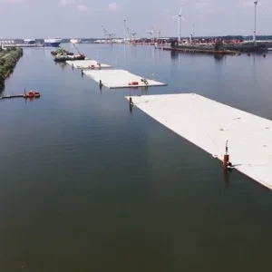
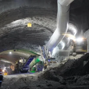
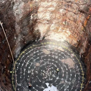
The Ashbridges Bay Treatment Plant is the largest of four wastewater treatment plants operated by the City of Toronto and is one of Canada’s largest and oldest wastewater treatment plants. The Ashbridges Bay Treatment Plant Outfall (ABTPO) project by the City of Toronto involves construction of a new tunnelled outfall that will convey treated effluent from the treatment plant into Lake Ontario. This new outfall will replace an existing outfall that is reaching the end of its service life and has limited hydraulic capacity. With only 1m of hydraulic head available at peak design flow under high lake water level conditions, the new ABTPO has been designed to minimize headloss and allow the outfall to operate by gravity with a design capacity of 3,923 million liters per day (MLD).
Outfall components consist of (Figure 1):
- An 85m deep, 14m internal diameter onshore shaft constructed adjacent to the shoreline;
- A 3,500m long, 7m internal diameter tunnel constructed through rock beneath the lakebed;
- Fifty 1m diameter risers installed in line with the tunnel extending from the tunnel horizon to the lakebed at equal spacing along the final 1,000m of the tunnel; and
- A new effluent conduit connecting the ABTP to the shaft.
The shaft will be initially excavated and supported with rock dowels and shotcrete. The tunnel will be excavated with a fully shielded (single shield) TBM and lined with a single-pass precast tunnel lining system. Following tunnel excavation, the shaft will be lined with a final cast-in-place lining.
The City of Toronto has engaged the services of Hatch in association with Jacobs and Baird to complete the preliminary design, detailed design, and construction management services during construction. In November 2018, the City of Toronto awarded the construction contract to Southland Mole of Canada and Astaldi Canada Design & Construction Joint Venture (SAJV). Construction of the ABTPO project commenced in January and will continue over the next five years, with final completion scheduled for January 2024.
1 Ground Conditions
Extensive geotechnical investigation was undertaken as part of the design of the ABTPO to characterize the anticipated ground conditions. At the shaft, overburden materials up to 20m in thickness are anticipated to be encountered consisting of sand, silt and clays overlain by landfill material associated with a historic reclamation area. Along the tunnel alignment, Georgian Bay Formation Shale (GBFS) is anticipated. An interpreted geologic profile for the ABTPO is shown in Figure 2.
2 Tunnel Lining
During preliminary design, a comprehensive study was completed by the designer to evaluate tunnel initial support and final lining alternatives consisting of either a two-pass cast-in-place (CIP) lining, or a single pass precast concrete tunnel lining (PCTL) system. A single-pass PCTL was chosen for this project on the basis of lower out-turn cost due to shorter schedule, acceptable Time Dependent Deformation (TDD) performance, superior durability and a safer working environment (control of gas inflow and fallout). A summary of the evaluation can be found in Table 1.
Detailed design proceeded with a single-pass PCTL system. As shown in Figure 3, the PCTL has been designed as a fiber reinforced universal ring consisting of six, 45-degree parallelogram segments, one 45-degree trapezoidal counter-key segment and one 45-degree trapezoidal key segment. Other features of the PCTL design include fully gasketed segments, radial bolt connections, guide rods along the radial joints, circumferential dowels and segment grout/lifting inserts.
2.1 Time dependent deformation
In the GBFS and other Southern Ontario shales, Lee and Lo (1993) describe three conditions required for TDD. They include 1) initial stress relief, which serves as the initiating mechanism, 2) the accessibility to fresh water and 3) outward salt concentration gradient from the rock’s pore fluid to the ambient fluid. Upon tunnel excavation (initial stress release), the in-situ stresses within the rock mass redistribute around the tunnel opening and elastic (and possibly inelastic) deformations immediately manifest themselves as inward convergence into the tunnel excavation. In rock that exhibits TDD behavior, the convergence deformation continues over time and the amount of TDD that occurs is a function of the TDD potential of the rock, the magnitude of stress relief and stress levels remaining within the rock (see Figure 4).
To address the TDD impacts, traditional tunnel practice in southern Ontario area includes a two-pass lining system (initial support during tunnel mining followed by the delayed installation of a CIP tunnel lining). However, analysis that incorporate the stress dependency of TDDs (Lo and Hefny, 1996, Hawlader et al, 2005, Kramer and Moore, 2006) indicates that, while the TDD behavior is anticipated to be more pronounced for a PCTL system (due to the short time lapse between excavation and support installation), the additional liner stresses are within the capacity of the system. Detailed TDD modelling was completed during design to ensure that the PCTL lining system could handle the additional load demand on the segments (Susetyo et al, 2018).
3 PCTL annular grout testing
As this tunnel is in hard ground, the annular space outside of the PCTL will not close around the lining. It is important that the annular void be completely filled to provide continuous contact between the PCTL and the rock mass to ensure the structural integrity of the installed PCTL. Failure to completely fill the void can create ring instability and overload the PCTL resulting in concrete cracks and impact the long term durability of the tunnel.
The contract specifications require that the annulus between the excavated tunnel and the extrados of the PCTL be filled continuously using two component cementitious grout with the advancement of the TBM. To ensure that the grout has been adequately produced and properly injected behind the lining, the design requires that contractor perform an annular grout test program followed by a check hole and contact grouting program.
The test program consists of drilling holes through installed PCTL rings (at a defined frequency) and observing the condition of grout. If voids exist, and or grout is insufficient, additional grout is injected by contact grouting. The grout test program and check hole procedure implemented on the ABTPO is a form of random sampling and follows common industry practice.
3.1 Ground penetrating radar (GPR)
Once commissioned, the new outfall tunnel is not anticipated to be dewatered nor taken out of service to allow for future inspections or tunnel repairs. As such, a Ground Penetrating Radar (GPR) survey, an innovative and non-destruction test method, will be performed following tunnel mining to increase the confidence in the quality of the installed tunnel lining. The GPR survey will confirm that the tunnel annulus has been fully grouted. Any anomalies (voids) discovered behind the lining or within the rock mass can be addressed with additional contact or consolidation grouting prior to commissioning.
The benefits of implementing the GPR scan include: 1) ability to verify the tunnel annulus using non-destructive techniques in comparison to the typical check hole procedure, 2) quick and accurate method for locating the position and depth of any void behind the PCTL and 3) capable of continuous data collection along with real-time results.
The use of GPR in tunnels has been used for evaluating concrete tunnel lining integrity and for confirming localized ground conditions, however the application of using this technology as a complete tunnel annulus grout quality assurance test has (to the authors' knowledge) never been implemented. The GPR scan on the ABTPO project will consist of a custom-built platform to accommodate the project’s tunnel diameter similar to that illustrated in Figure 5.
4 Instrumentation
The ABTPO project requires shaft and tunnel instrumentation to be installed during construction to monitor ground movements within overburden material and GBFS, and to monitor loads on temporary structures and final lining elements. Where possible, tunnel and shaft instruments are specified as vibratory wire capable of being data logged. Data logging provides the ability to capture a complete time-history over the entire construction duration. This eliminates the need for manual reading and provides a safer means of obtaining the data by allowing the data logger to be located in a safe and convenient location.
4.1 Tunnel instrumentation
Tunnel instrumentation arrays have been specified to be installed in six locations along the tunnel at a nominal 500m spacing. Each tunnel array consists of strain gauges, pressure cells, mini-prism targets and single point borehole extensometers (SPBX). A typical tunnel array is illustrated in Figure 6.
Given that the PCTL system is required to support the additional load demand due to TDD, it is critical to accurately monitor ground deformations behind the tunnel lining and stresses within the PCTL system to validate design assumptions made with respect to TDD impacts on the final tunnel PCTL lining. To satisfy these requirements, the ABTPO includes an innovative instrumentation design, whereby actual PCTL segments will be instrumented.
The pressure cell is to be field mounted on the segment extrados prior to ring erection and the strain gauges are to be located near the segment intrados and extrados and embedded in the segment during PCTL manufacturing. Figure 7 illustrates the instrumented segments, which consist of three strain gauges and one load cell. To the authors’ knowledge, this is the first application of instrumented segments within North America for the purpose of measuring TDD impacts. SPBXs will be installed near the tunnel crown and at the tunnel springline and includes both a 1m- and a 2m-long SPBX for the purpose of comparing movements at a distance from the tunnel excavation.
Due to the size of the ABTPO tunnel, mini-prism targets have been specified in-lieu of traditional tape-extensometer points to measure tunnel diameter, squatting and deformations in the installed PCTL ring.
4.2 Shaft instrumentation
Within the overburden materials, standard deep excavation instrumentation has been specified consisting of piezometers to monitor groundwater conditions and inclinometers to monitor lateral ground movements concurrent with shaft and conduit excavations. Two types of inclinometers have been specified including in-ground borehole installations and installation within support of excavation elements (e.g., secant piles).
Within the GBFS, three shaft instrumentation arrays have been specified, nominally spaced vertically at intervals of 15m.
A typical shaft instrument array is shown in Figure 8 and consists of SPBXs, pressure cells, rock dowel load cells and mini-prism targets. SPBXs will be installed in pairs extending 1m and 2m beyond the shaft wall and will be used for measuring ground movement behind the excavation. Pressure cells will be installed within the temporary support shotcrete layer and will measure the load on the temporary support.
Similarly, load cells will be installed on select rock dowels within the shaft for the purpose of recording loads in the rock dowels. Due to the size of the ABTPO shaft, mini-prism targets have been specified in-lieu of traditional tape-extensometer points to measure shaft diameter convergences. Shaft monitoring results will be closely reviewed to confirm appropriateness of design assumptions for both the temporary and final lining.
5 Conclusions
The design for the ABTP Outfall project posed several design challenges that were addressed by implementing a number of design innovations. These innovations included the first-time application of instrumenting PCTL segments for measuring time dependent deformations and the implementation of non-destructive test methods as quality assurance tools for checking the final installed precast concrete tunnel lining.
Once commissioned, the ABTP Outfall tunnel will allow the City of Toronto to operate the plant at all design flow conditions without hydraulic limitations and will allow the City to meet the current requirements for effluent dispersion.
It will also significantly improve the water quality of the Toronto lakeshore and surrounding community.


