


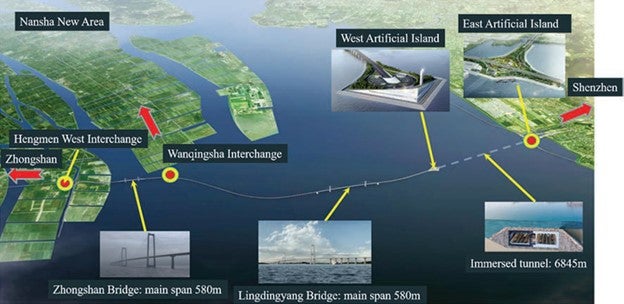
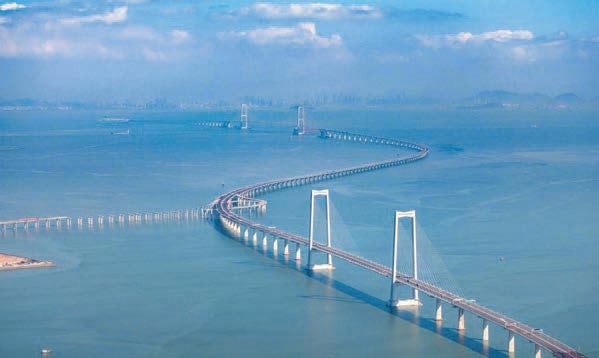
The Shenzhen-Zhongshan (Shen-Zhong) fixed sea link across the Pearl River estuary in China is nearing completion and has conditions for opening to traffic in June 2024. This complex infrastructure project comprises bridges, tunnels, and artificial islands, and is strategically positioned approximately 40km upstream of the Hong Kong-Zhuhai-Macao (HZM) tunnel and bridge link, which commenced highway operations in 2018, and it is also 38km downstream of the Humeng Bridge, another crucial link established in 1997 (see Figure 1).
Spanning a distance of 24km, the Shen-Zhong link seamlessly connects Shenzhen in the east to the cities of Zhongshan and Guangzhou Nansha in the west. Notably, the route traverses three heavily trafficked shipping channels, accommodating more than 4,500 vessels daily.
The link comprises a highway with four lanes in each direction, totalling eight lanes, featuring a distinctive segment with six lanes in each direction. It is engineered for a traffic speed of 100km/h and a design life of 100 years. The project’s primary components include a suspension bridge with a main span extending 1,666m, a cable-stayed bridge with a main span of 580m, and the link transitions to run below the seabed in a 5km-long steel immersed tube structure (see Figure 2) between two man-made islands. Additionally, a 485m-long cutand- cover section extends from the east landfall near Shenzhen (see Figure 3). Notably, the tunnel at the east end must adhere to the clearance limitations dictated by the flight path of Shenzhen International Airport.
The immersed tube section between the east and west man-made islands (of about 370,000m2 and 130,000m2, respectively), consists of 32 elements that have dimensions 10.6m high x 46m~55.5m wide x 165m/123m long, and a 2.3m long closure joint.

After approximately six years of construction, the mega fixed sea link, comparable in scale to the recent HZM project, stands at over 95% completion. As members of the Shen-Zhong Link Management Center owner organisation, the authors discuss the design and construction of the widest steel immersed tube tunnel globally.
EAST AND WEST ARTIFICIAL ISLANDS
The construction of the west man-made transition island, the east island and the connected 485m-long cut-and-cover section utilised two distinct methods tailored to their respective conditions.
The west island and the cut-and-cover section were completed prior to the lowering of the immersed tube elements for E1 and E32, respectively.
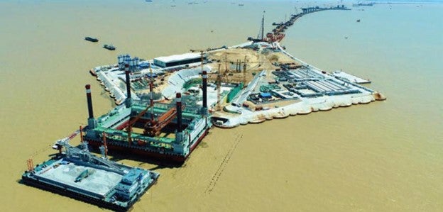
The east island, close to the Shenzhen coastline, passes under the Guang-Shen Riverside Highway viaduct (see Figure 4). The minimum distance between the outside surface of the tunnel on the island and the viaduct pier foundation is only 2.4m. To safeguard its continuing operation, the highway owner required the maximum horizontal displacement of less than 5mm for the 41 support piers that lie within the island with max. 17m-deep pit. In this area, the water depth measures approximately 4m, and the underlying soft soil ranges in thickness from 8m to 15m.
Traditional methods for constructing artificial islands involve either improving or removing the soft soil beneath the seabed, followed by the deposition of selected fill materials to establish a stable foundation. The island’s construction spanned three years, employing a slow sand-fill approach to protect the integrity of the surrounding piers. Piers situated near the tunnels were encircled by steel pipes with diameters of 1.4m/1.5m, filled with reinforced concrete to serve as retaining structures, while steel sheet piles were utilised to safeguard other piers.
Enhancing safety during the excavation of the foundation pits, a steel support axial force automatic servo system was employed. This system boasts functionalities such as automatic control, real-time monitoring, and automatic compensation, effectively mitigating issues such as axial force loss attributed to temperature fluctuations, stress relaxation, and plastic deformation. Successfully applied to deep foundation pit projects adjacent to bridge piers, this system has yielded commendable results.
Located approximately 6km from the Shen-Zhong coastline, the west island faces a maximum water depth of about 10m. To align with the overall project timeline, vibration piling techniques, akin to those developed for the HZM project, were deployed (see Figure 5). This involved the insertion of 57 steel cylinders, each measuring 18mm in thickness, with dimensions of 28m in diameter and 40m in height.
Ensuring stability and waterproofing necessitated penetrating the completely weathered rock zone, posing a challenge due to the stiffness of the steel cylinders. Preparation of the area involved the utilisation of specialised blender equipment to fracture the bedrock and introduce bentonite into the zone. Auxiliary cells were subsequently inserted to interconnect the adjacent cylinders, forming a temporary impermeable wall. This enabled the seawater within to be evacuated, facilitating sand-filling and the installation of vertical drains inside the wall on the island to achieve surcharge/ precompression. The adoption of the cylinder wall method condensed the island construction period to five months.
TUNNEL FOUNDATION
A pre-paving technique has been implemented to establish the foundation of the immersed tube tunnel section within a trench excavated to a maximum depth of 36m below sea level. This foundation incorporates a double-bedded structure, featuring a 1m-thick graded aggregate cushion and a 1.1m-thick layer of rock levelling. The ground improvement process involves the use of deep cement mixing (DCM) piles, providing support for nine elements. A double/single bedded foundation layer of 1m-thick graded aggregate cushion and partial rock tamping and levelling supports the other 23 elements above the natural seabed (see Figure 6).
The DCM piles, reinforcing the soft ground, are executed from specialised barges and utilise cement as the curing agent. Cement slurry is pumped and poured into the soil, mixed with specialised machinery to form a homogeneous cement-soil mixture. This process significantly enhances the foundation’s strength through the hydration reaction of the cement and chemical interactions between the materials. In adherence to design specifications, the 60-day mean unconfined compressive strength of the DCM piles is required to be no less than 1.2MPa.
STEEL-CONCRETE-STEEL (SCS) STRUCTURE
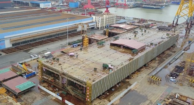
To accommodate the fabrication of the maximum 55m-wide element, the conventional reinforced concrete structure is inadequate. Therefore, the Steel- Concrete-Steel (SCS) composite structure, initially introduced for immersed tube projects in Japan, was selected. It comprises inner and outer steel panels as the primary flexural members, along with transverse and longitudinal diaphragms serving as the main shear members, all interconnected with stiffeners and welding nails (see Figure 7). The panels and diaphragms form an enclosed chamber for concrete pouring, with dedicated pouring holes and exhaust holes provided.
Following concrete placement, water sealing is imperative. Longitudinal stiffeners, composed of T-shaped steel and angle steel, in conjunction with welding nails, serve as shear connectors, ensuring robust connections between the panels and the infill concrete. The combined action of longitudinal stiffeners and transverse flat ribs enhances the panels’ stiffness. Given that concrete is confined within the steel chambers, the use of high-flowability and selfcompacting concrete is essential to facilitate proper placement and consolidation.
Given that the SCS composite structure is being implemented for the first time in China, several challenges have needed to be addressed. A systematic approach was adopted, involving experiments and analysis of mechanical mechanisms and design methodologies. Through these investigations, the behaviour of the SCS structure under bending and shearing was elucidated, and corresponding analysis methods were developed. Furthermore, the impact of the gap between steel plates and concrete on the bearing capacity was quantitatively assessed, leading to the proposal of quality control standards for concrete casting.
Experiments with SCS steel chambers and a fullscale model of 18m long x 46m wide x 10.6m high were performed to confirm the types and strength grades of materials, design of steel chambers and details of design requirements. The concrete quality can be met when the flow speed of concrete is limited to 30m3/ hr ~40m3/hr to a 20cm clearance between the face of concrete and upper steel plates in the steel chamber, and limited to 15m3/hr after that. Additionally, the density of concrete should be controlled in the range of 2,300kg/m3~2,370kg/m3.
CLOSURE JOINT
The final closure joint of the tunnel, positioned between elements E23 and E24, marks a critical point where the depth of the element invert reaches -15m below sea level.
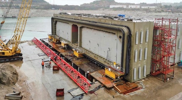
This closure joint is a specialised prefabricated component featuring a 2.3m-long push-out section (see Figure 8), designed to match the standard cross section of the adjoining elements. Despite demanding manufacturing precision, this structure offers several advantages:
- Enhanced safety during the flotation and sinking operation.
- Reduced demands on temporary channels and equipment.
- Decreased reliance on diving operations.
- Accelerated installation speed.
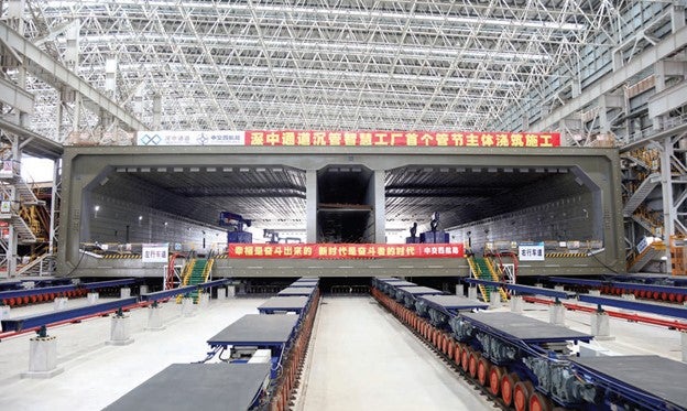
ELEMENT FABRICATION WORKSHOP
The total steel plate consumption for all 32 elements amounts to approximately 320,000 tonnes. This represents the first large-scale utilisation of steel plates for immersed tube tunnels, underscoring the critical importance of maintaining fabrication quality and cycle control.
Contracts for manufacturing the 32 elements were distributed among two ship manufacturers due to the resemblance of construction methods, technology, and inspection standards to shipbuilding practices. Aligned with the construction schedule, the fabrication of these 32 elements was slated for completion within 36 months.
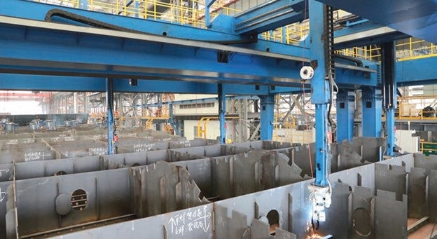
Leveraging the integration of industrialisation and digitised data management, the overall fabrication process is centred on the principles of smart manufacturing for steel structures. In efforts to bolster work efficiency and ensure quality, the two manufacturing contractors were tasked with establishing a smart workshop, implementing the ‘four lines and one management system’. This system encompasses a smart plate cutting line, a smart plate welding line, a smart block welding line (see Figure 9), and a smart painting line, and also a comprehensive workshop management and control system.
ELEMENT CASTING FACTORY
To ensure efficient project management, the construction process – encompassing concrete pouring, first and second outfitting, flotation, and installation – is divided into two separate bids:
- Bid 1 encompasses elements E1 to E23 and the closure joint, with the element casting facility located at the same site as the HZM immersed tube project, albeit renovated.
- Bid 2, covering elements E24 to E32, operates within the dock of a shipyard where steel structures were prefabricated.
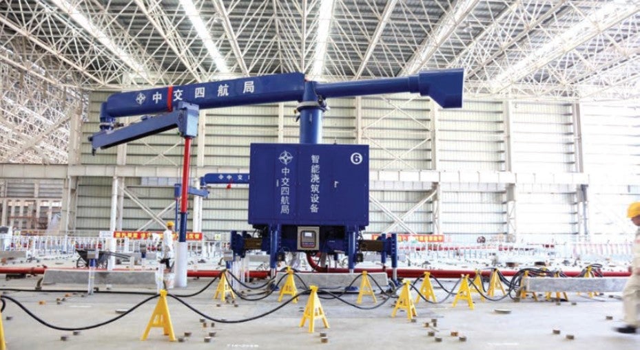
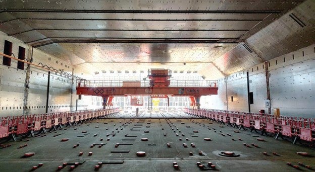
For Bid 1, the concrete pouring process is managed by a stable smart system equipped with an automatic hole-finding function (see Figure 10). Upon completion of concrete pouring in one chamber, the system seamlessly transitions to the next pre-set chamber with the required precision. The pouring equipment and trailer pump are synchronised via two-way wireless communication, enabling automated start and stop of the pouring process. Additionally, concrete flow speed adjustments and pump tube elevation, based on liquid level feedback, are conducted to ensure proper concrete placement and prevent the outlet of the pump hose from being buried.
Bid 2 employs an alternative concrete pouring system (see Figure 11).
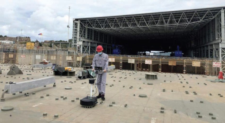
Two detection methods are employed to identify voids beneath the upper steel plates (maximum 4cm-thick) and between transverse and longitudinal diaphragms, stiffeners, and welding nails. The first method is an enhanced impact imaging technique, scanning all upper plates atop the SCS elements to identify potential void areas (see Figure 12). The neutron method is subsequently employed to re-scan areas with suspected voids. These two methods achieve high accuracy, with an average void height accuracy of 2.5mm for a 10cm x 10cm area and a detection efficiency of approximately 90% for void locations.
ELEMENT INSTALLATION
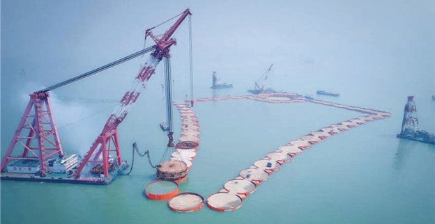
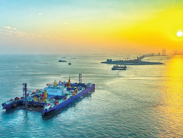
For elements E1-E23 and the closure joint, situated up to 50km from the tunnel site, and with the approximately 21km along the Lingding Channel, one of the world’s busiest channels, it was imperative to minimise disruption to shipping.
To achieve this, flotation and installation activities were conducted without the need for total or partial channel closure. A self-propelled vessel, boasting substantial dimensions and a maximum velocity of 9km/hr, was engineered to seamlessly integrate the flotation, immersion, and installation functions for the elements (see Figure 13).
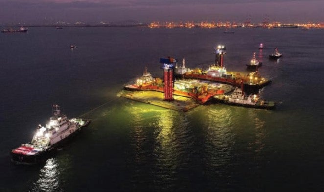
Conversely, for elements E24-E32, with approximately 21km distance from the dock to the tunnel site, traditional towing and immersion methods were employed. This involved the utilisation of eight boats for towing operations. A novel control system has been developed to monitor the real-time position of the tunnel element and all tugboats, ensuring effective coordination and preventing the towed element from straying more than 10m from the centreline of the dredged channels (see Figure 14).
SUMMARY
As one of China’s most pivotal and challenging infrastructure undertakings, the Shen-Zhong Link has served as a driving force for innovation in both the design and construction realms (see Figure 15). The adoption of the Steel-Concrete-Steel (SCS) composite structure has revolutionised the construction of wider and longer immersed tunnels, offering substantial advantages.
Furthermore, a comprehensive set of codes and specifications governing the design, construction, and quality inspection processes have been implemented to ensure adherence to rigorous standards. The project has also been instrumental in the advancement of digitised construction technologies, enabling the resolution of technical challenges, enhancement of engineering quality, and mitigation of construction risks.
Similar to the groundbreaking impact of the HZM project preceding it, the Shen-Zhong project is once again pushing the boundaries of planning, design, and construction for mega fixed links across the seas, setting new standards, and inspiring future innovations in the field.


