1. INTRODUCTION
London’s rapidly growing population, now around nine million, has placed significant strain on the city’s critical infrastructure. The existing sewer network, designed by Sir Joseph Bazalgette in the Victorian era over 150 years ago, remains a remarkable feat of engineering but was built to serve a much smaller population. Today, it has capacity for less than half of London’s residents. As a result, millions of tonnes of untreated sewage are discharged into the River Thames during periods of rainfall, causing severe environmental damage and water quality issues.
To address this challenge, the Thames Tideway Tunnel, aptly named the ‘Super Sewer’, was conceived. The project intercepts sewage at 34 of the most polluting combined sewer overflows (CSOs), where flows would historically spill directly into the river, and divert them into a new tunnel system.
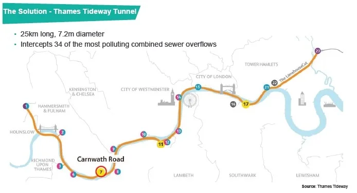
The tunnel is 7.2m-diameter and extends 25km from Acton in West London to Abbey Mills Pumping Station, in East London. At Abbey Mills, it connects into the Lee Tunnel, which conveys flows to Beckton Sewage Treatment Works. The route, shown in Figure 1, generally follows the profile of the River Thames, varying in depth from 31m below ground level, in the West, to 70m in the East, with flows gravity fed along the network at a gradient of 1m per 790m.
The project represents an estimated £5 billion investment and is scheduled for completion over a tenyear period from 2016 to 2026.
Construction of the tunnel was divided into three main sections, reflecting the varying ground conditions along the route, and delivered by three joint venture partnerships. The West section, constructed through predominately clay soils, was undertaken by BMB JV (Bam Nuttall, Morgan Sindall and Balfour Beatty). The Central section, delivered through sands, was managed by FLO JV (Ferrovial and Laing O’Rourke). The East section, constructed through chalk, was delivered by CVB JV (Costain, Vinci and Bachy). Each section comprises the main tunnel, connection tunnels, interception shafts, hydraulic chambers and drive shafts.
I was based at Carnwath Road Riverside (CARRR), the principal drive site for the West section. This location served as the launch shaft for the tunnel boring machine (TBM) that mined 7km West to Acton. My involvement provided direct exposure to large scale tunnelling and shaft operations working within a major joint venture partnership.
This report presents the shaft secondary lining works at CARRR, which involved 330 concrete wagons delivering more than 2250m3 of reinforced concrete that was poured continuously over a 26-day period. In addition to outlining the construction techniques employed for the installation of the lining, the report examines the specific challenges encountered during the works.
2. SHAFT SECONDARY LINING
2.1. Carnwath Road shaft
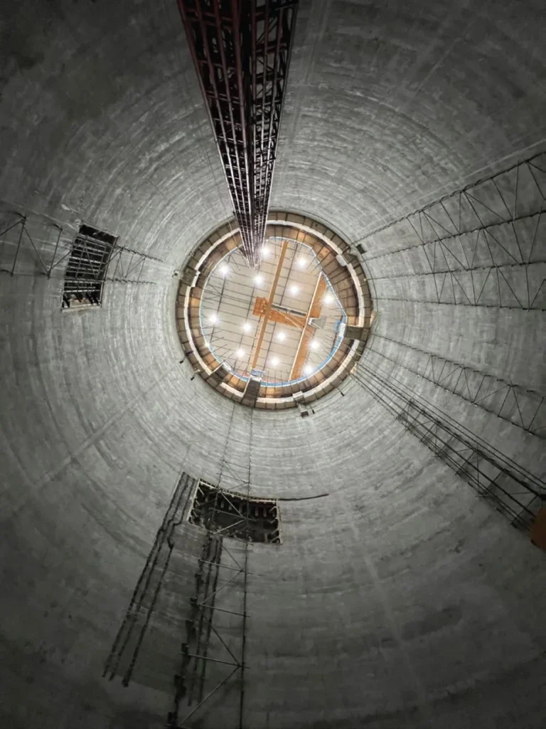
The shaft at CARRR was 41m-deep with a 25m-internal diameter once the final concrete lining had been cast. During shaft sinking, a secant pile wall was first constructed to provide cut-off protection against water ingress within the upper water bearing strata. The excavation itself was formed to a diameter of 28.3m. The primary lining comprised a 1.05m thickness of sprayed concrete lining (SCL), reducing the shaft diameter to 26.2m. The secondary lining was subsequently installed, consisting of a 0.6m thickness over a depth of 38m, extending from 61.797m Above Tunnel Datum (ATD) to 99.900m ATD. Above this level, where no primary lining was present, the secondary lining was increased to 1.2m in thickness, continuing up to 103.098m ATD.
2.2. Design of secondary lining
The shaft secondary lining was designed with a 120-year service life and specified as a watertight structure. Any leakage into the shaft would create a pathway for sewage to migrate through the walls into the surrounding ground, leading to contamination of adjacent soils.
To meet the watertightness requirement of 0.1 l/m2/ day, the lining design combined B25 steel reinforcement at 200mm spacing with steel fibre reinforced concrete, following testing. Double reinforcement was specified to limit cracking. Although designers explored removing conventional reinforcement, to reduce the carbon footprint of the lining, this option failed to maintain early age crack widths below the 0.2mm limit and frequently produced flexural strength values below the required 5MPa during testing.
The concrete mix adopted was CM4a, specified with cube strength C40/50. The mix incorporated limestone aggregate with a maximum size of 20mm and CEM III/ A+SR cement to provide enhanced sulphate resistance. A 40% GGBS replacement was included, together with 40kg/m3 of steel fibres, ensuring durability, strength, and watertightness for the long-term performance of the shaft lining.
2.3. Methodology for shaft secondary lining
A slipform technique was selected for the pouring of the shaft secondary lining to minimise construction joints and achieve the highest possible level of watertightness. The principle of slipforming involves a continuous supply of concrete poured into the shutter at the top, which cures at the bottom, allowing the shutter to steadily rise. Concrete was placed in uniform layers at a rate of 200mm/hr, providing sufficient time for the lower section to harden while maintaining a climbing speed equal to the initial set time of the mix. As the process was continuous, the concrete remained live throughout, thereby eliminating construction joints.
The slipform rig comprised a three deck system supported by six-tonne jacks mounted on steel circular hollow section climbing tubes. The operator hydraulically controlled the jacks to advance the rig once the concrete at the base of the shutter had adequately cured. In total, 24No. equally spaced climbing tubes were installed, each capable of carrying 500kg, giving a combined live load capacity of 12 tonnes. These tubes were cast into the middle of the secondary lining and provided structural support during the slipforming operation.
The rig’s top deck was used primarily for steel fixing and preparatory works, the working deck facilitated the pouring of concrete into the shutter, and the hanging deck beneath the shutter provided access for finishers to carry out concrete repairs. Access to the rig was primarily via a lift, with a manrider available as a secondary means of egress.
During my shift, I served as the lead engineer on the slipform rig. My responsibilities included managing the workforce across all decks and coordinating the continuous supply of concrete required to maintain uninterrupted movement of the rig. Effective communication was essential to the success of the operation, ensuring that each stage of the process was executed safely and efficiently. As this was my first experience working with a slipform, the project provided a significant learning opportunity and valuable exposure to complex construction techniques.
2.4. Slipform preparation works
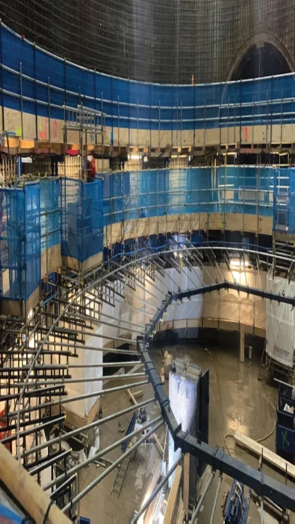
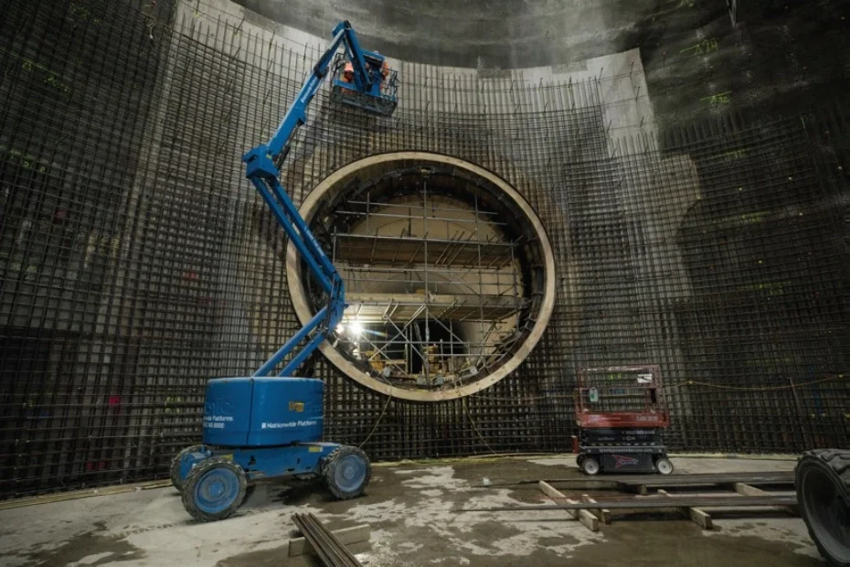
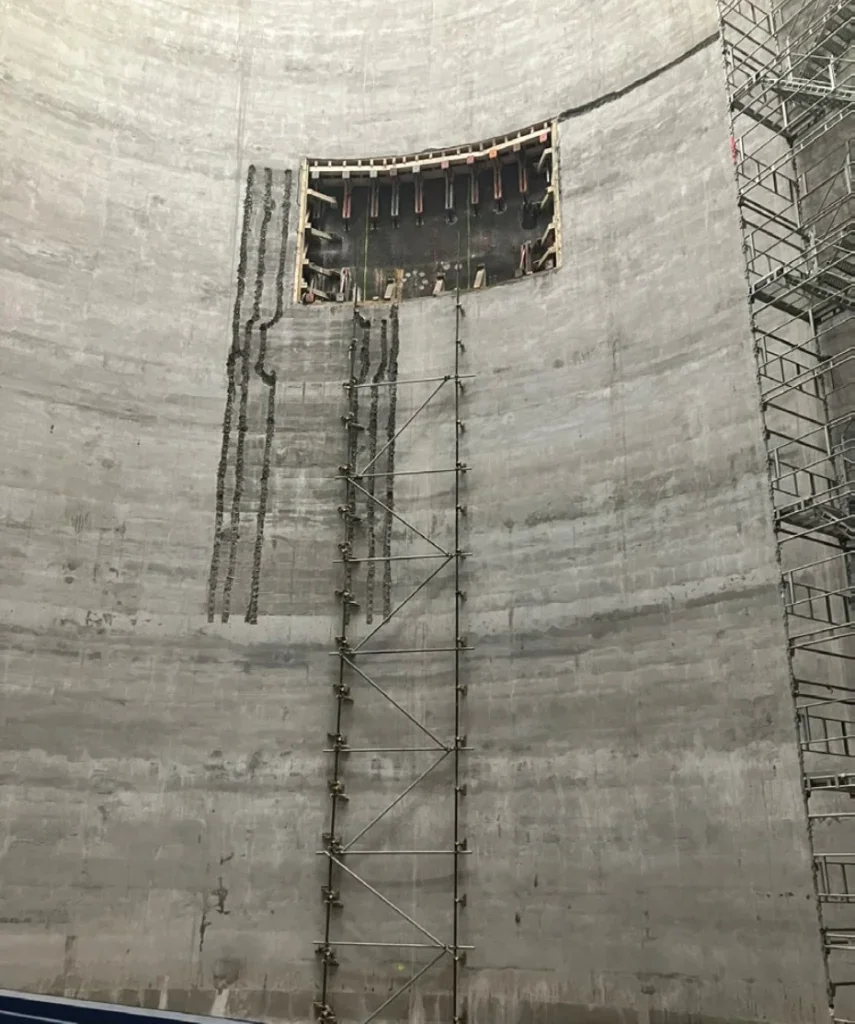
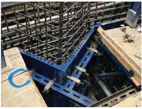
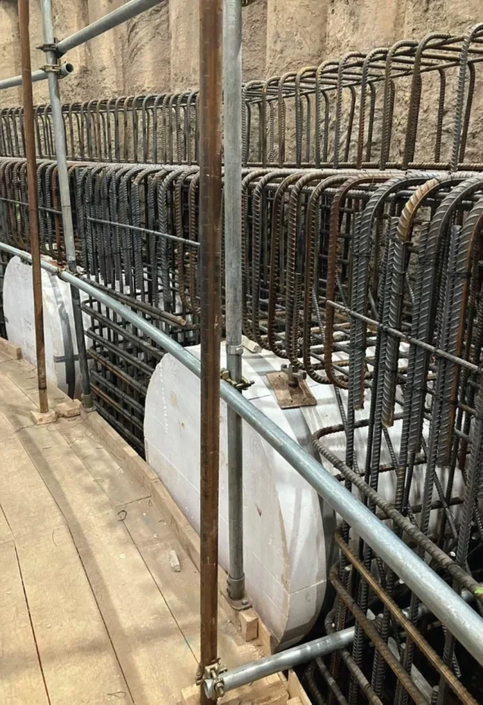
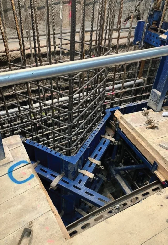
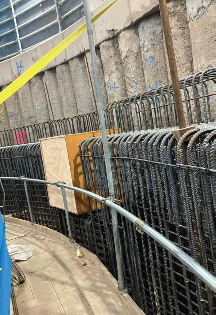
Prior to starting the slipform, extensive preparatory works were required. A key element involved the installation of two drum shutters around the tunnel portals that the shaft secondary lining would be formed around, Figure 3. I was responsible for setting out the position of the C24 timbers and marking the angles at which they were to be cut, given that the tunnels entered the shaft at an angle. Accurate setting out was critical to ensure the slipform rig could pass the portals without obstruction, while also providing sufficient structural depth for the concrete lining to be formed around. Additional boxouts were installed higher in the shaft to accommodate the mid-level connection tunnel, which tied into the primary lining. Careful attention was given to the setting out of these features to avoid potential issues during later stages of construction.
To achieve the required watertightness, all leaks in the primary lining were injected prior to the slip, maximising the likelihood of sealing the shaft. The shaft was jet washed to remove dust and all fixings were cleared. I managed this process across shifts, ensuring no areas were overlooked through effective handovers and by delegating specific sections of the shaft to different teams. I sprayed reference levels every 2m up the shaft, providing clear markers once the slipform commenced. These levels were essential for identifying changes in reinforcement, scheduling the installation of cast-in items, and monitoring daily progress. Reinforcement zones were also marked directly on the rig to assist steel fixers as well as the locations that required rig alterations at the top of the shaft.
By maintaining a proactive approach to preparation, the slipform was able to progress smoothly, with all personnel having a clear understanding of upcoming requirements, particularly where cast-in items and rig modifications were involved. This forward planning created additional capacity to address inevitable issues during the slip, which is inherently a fast-paced operation with limited opportunity for downtime.
2.5. Installing the steel reinforcement
Steel reinforcement pre-fixing was undertaken to reduce the workload on the steel fixers at the start of slipforming and to ensure the correct positioning of the starter bars. Using the TunnelBeamer, a tablet loaded with the finished shaft profile, I set out the bars to maintain the specified 75mm cover and the required 200mm bar spacing. This task demanded careful interpretation of the complex reinforcement drawings. The positions of the near and far face reinforcement were marked on pins installed into the primary lining, allowing accurate placement of the vertical bars despite variations in lining thickness. I carried out routine checks throughout the process and communicated directly with operatives whenever adjustments were necessary. By ensuring accuracy at the outset, the reinforcement was correctly aligned, which facilitated smooth progress during slipforming and eliminated positional issues with the steel.
2.6. Survey control
As the slipform rig advanced up the shaft, the control prisms located at the top would become obstructed. To mitigate this, I installed additional survey control points into the base slab prior to commencing slipforming. I also tested the instrument setup in several key locations that I anticipated would be required during the operation. By uploading all survey data onto the EDM and establishing the most effective setups in advance, I was able to share this information across shifts. This proactive approach reduced potential obstructions during the slipform process and ensured that concrete pouring could continue without interruption.
2.7. Emergency procedures
Due to the significant changes to the working area prior to commencement of the slipform operation, a series of emergency procedures were carried out. I marked out designated clear zones for the emergency manrider and conducted injured person trials to validate rescue arrangements. Following these trials, I recommended enlarging the access hatch to facilitate the safe and efficient recovery of an injured person from the hanging deck, thereby improving response times in the event of an incident.
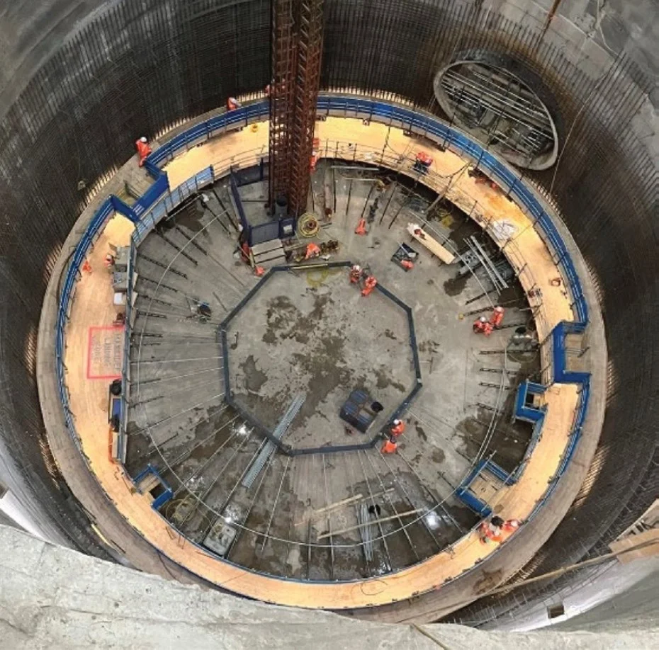
The complete rig is shown in Figure 4, which highlights the location of the emergency stretcher zone on the left-hand side. In addition, I instructed the carpenters to construct shelving for the storage of MSA units. This ensured that all personnel were aware of the location of life saving equipment and reduced the risk of trip hazards caused by devices being left unsecured on the deck.
3. SLIPFORM OPERATION
The slipform operation was delivered under a 7/4/7/3 shift pattern, with each shift lasting 12 hours. The gangs worked seven consecutive days, followed by four days off, then seven consecutive nights, followed by three days off. Three shifts were maintained daily, comprising a day shift, a night shift, and an off shift, with site hours running from 07:00 to 19:00. Handover at the face was critical to ensure continuity of the slipform process. Each gang consisted of six steel fixers, six carpenters, six concrete operatives, two concrete testers, one pump driver, three slingers, a foreman, and two engineers.
On average, each shift poured approximately ten wagons of concrete, equating to 75m3, which enabled the slipform rig to climb by roughly 1.5m per shift.
The most productive shift achieved 13 wagons, nearly 100m3, due to reliable concrete supply and a simpler reinforcement arrangement. Steel fixers installed around six tonnes of reinforcement per shift, contributing to a total of 350 tonnes of conventional reinforcement fixed during the full lining. Carpenters worked from the top deck to install cast-in items and cleaned the shutter with scrapers, a critical activity to maintain a high-quality concrete finish. Any hardened concrete left on the shutter risked scouring through fresh concrete, resulting in avoidable repairs.
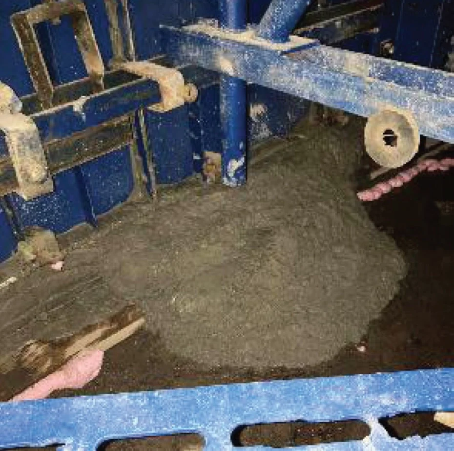
During the initial jacking of the rig, once the shutter had been filled by 800mm, premature movement up the shaft caused a minor spillage as the concrete at the base had not yet achieved sufficient early strength, Figure 5. This was attributed to slower curing than indicated by site trials. I monitored for leaks during the initial jacking at pit bottom and instructed the operator to delay jacking until curing was complete. On the subsequent attempt, the concrete had set adequately, and the slipform progressed without incident.
Concrete ordering and coordination were managed through a WhatsApp group, providing visibility to surface teams, shaft operatives, and the following shift. This ensured all information was in one location, including slump test results, which allowed adjustments to be made to achieve the desired consistency. While on the rig, I pre-warned operatives about load consistency and advised them of wagon arrival times, supported by Tarmac’s GPS tracker. This system proved valuable during delays, enabling the slipform supervisor to adjust jacking speed accordingly. Depending on supply frequency and site progress, the section manager controlled the addition of retarders to improve finish quality and reduce the need for repairs.
Concrete testers measured every wagon upon arrival. Slump values were targeted to within the range of 140mm to 230mm, and strike cubes were taken every 50m3. If a load failed the slump test, the procedure was to allow it to stand for 30 minutes before retesting. Loads failing a second test were rejected. This rigorous quality control ensured that all concrete poured exceeded the specified cube strength of 50 MPa.
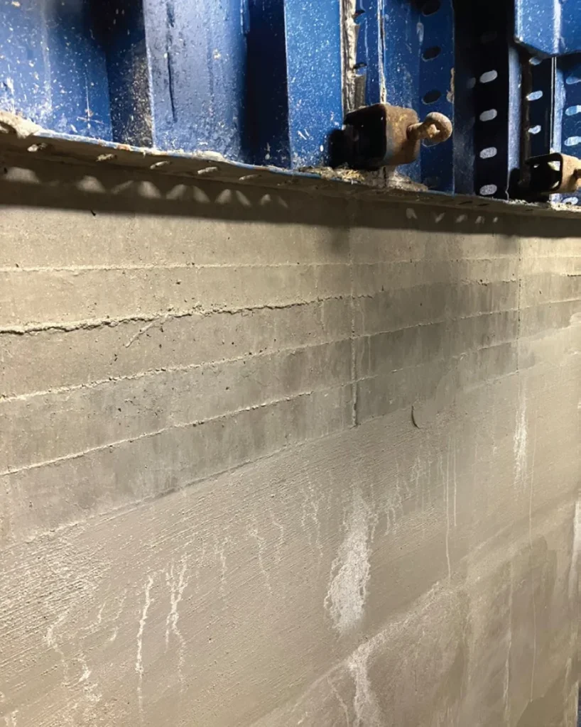
When higher slump concrete loads arrived on site, the material required longer to achieve initial set. As a result, the rate of rise had to be carefully managed to prevent bulging at the base of the shutter. Conversely, concrete that was too dry produced a poorer surface finish. Achieving the correct balance between consistency and rate of rise was therefore critical. For the fibre reinforced mix CM4a, the typical rise rate was maintained at approximately 200mm/hr, which provided sufficient clearance at the top of the shutter while allowing adequate curing time. The slipform supervisor controlled this by jacking the rig in 50mm increments every 15 minutes, with the resulting layers illustrated in
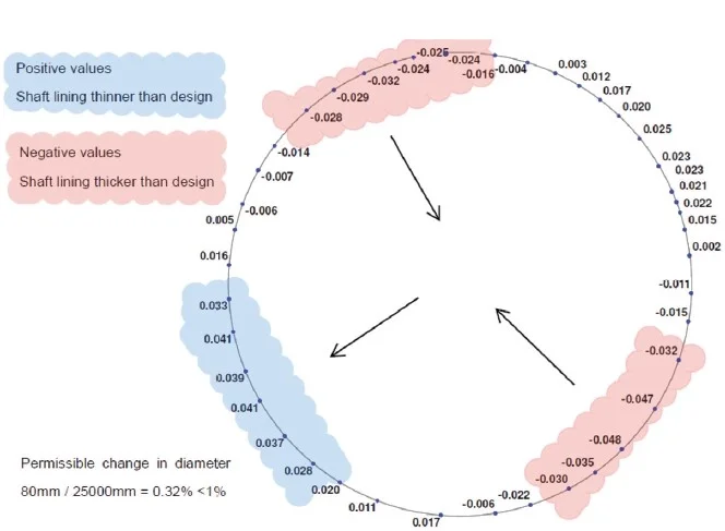
Figure 6. Although a longer shutter could theoretically permit a faster rise rate, it would also increase the rig’s weight, requiring additional bracing and jacks.
Another key limiting factor in jacking the rig was the need to balance steel fixing, carpentry, slipform movement, and concrete placement. At different stages of the operation, each discipline became the critical activity, making collaborative working and clear communication essential. I maintained constant dialogue with all gangs to ensure the slipform progressed as planned. At the start of each shift, I met with the chargehands to outline my setting out plan and to identify any urgent requirements, which was particularly important when I was the sole engineer on site.
By monitoring the arrival of concrete wagons, I identified suitable gaps in supply to land reinforcement onto the deck, improving efficiency and continuity of work. In the fast paced environment, where multiple activities were occurring simultaneously, clear and coherent communication was vital. For the slipform to operate successfully, the rig had to function as a well coordinated system, with stoppages used productively to address outstanding tasks. The most challenging aspect was ensuring a consistent supply of reinforcement for the fixers. As the rig could not be overloaded, reinforcement had to be landed in a controlled, ‘drip fed’ manner between concrete wagons to maintain workflow continuity.
3.1. Vortex coupler installation
One of my principal responsibilities was setting out the position and angle of nearly 500 couplers cast into the secondary lining, Figure 7. All data were uploaded onto the EDM and a clear mark-up was produced in advance, ensuring efficient installation and reducing the risk of accidents caused by rushed work. I mounted a large, laminated drawing adjacent to the installation area, allowing installed couplers to be ticked off and enabling all shifts to track progress consistently.
Occasionally couplers clashed with the slipform climbing tubes. It was essential to understand the connecting structures to relocate them appropriately. Recognising that the external couplers were most critical in terms of cover, I adjusted the positioning of inner couplers where necessary to maintain compliance.
Couplers were protected with foam and subsequently exposed on the hanging deck, which also served as the location for concrete repairs. To streamline repair documentation, I devised a clock-face system referenced to the tunnel portals. This provided a simple and reliable method of recording repair locations, which proved particularly valuable when working on the rig as you would lose track of where you were.
3.2. Movement of the rig
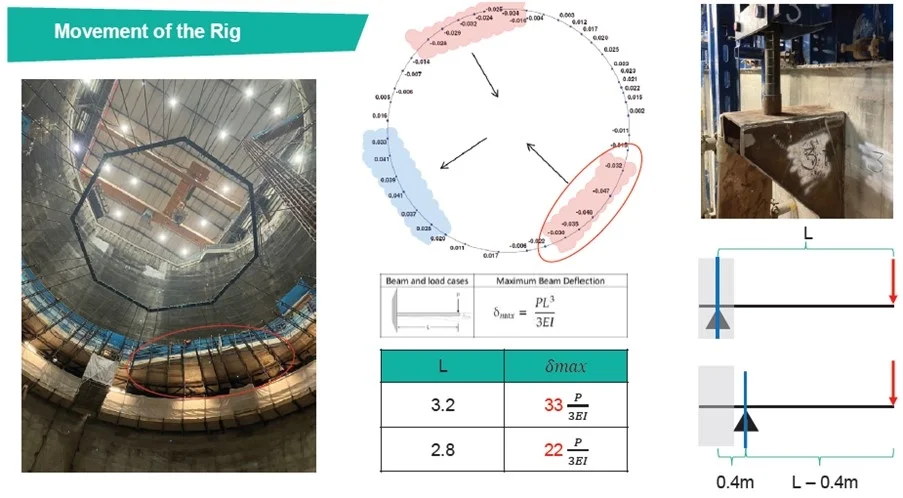
At the end of each shift, I used the TunnelBeamer to record an as built survey in order to monitor how the slip finished concrete was deviating from the design profile. The survey data were presented in a clear diagram, Figure 8, and the number of survey points was increased whenever readings indicated potential concern.
The results quickly highlighted that the rig was ovalising. This deformation was likely influenced by the two tunnel portal openings, where the forces acting on the rig differed, or by the slower placement of the initial wagons, which caused uneven filling of the shutter. However, the primary factor appeared to be the widened section of the deck used for landing reinforcement. This additional loading increased the cantilever effect, effectively pulling the rig outward. The affected area is highlighted in red in Figure 8 and Figure 9.
To realign the rig with the design position, the climbing tubes were relocated from being cast within the concrete to installation on the inside face of the completed secondary lining, as illustrated in Figure 10. This modification was intended to reduce the effective cantilever length. A simplified calculation, carried out from first principles, confirmed that the adjustment would have a beneficial effect.
The deflection of a cantilever is directly proportional to the cube of its length (L3). Therefore, reducing the cantilever length significantly decreases deflection. Calculation showed that shortening the cantilever length by 0.4m, from 3.2m to 2.8m, reduced the maximum deflection by approximately 33%, from 33P/3EI to 22P/3EI (where P is the load, E is Young’s Modulus, and I is Moment of Inertia of the Cross Section).
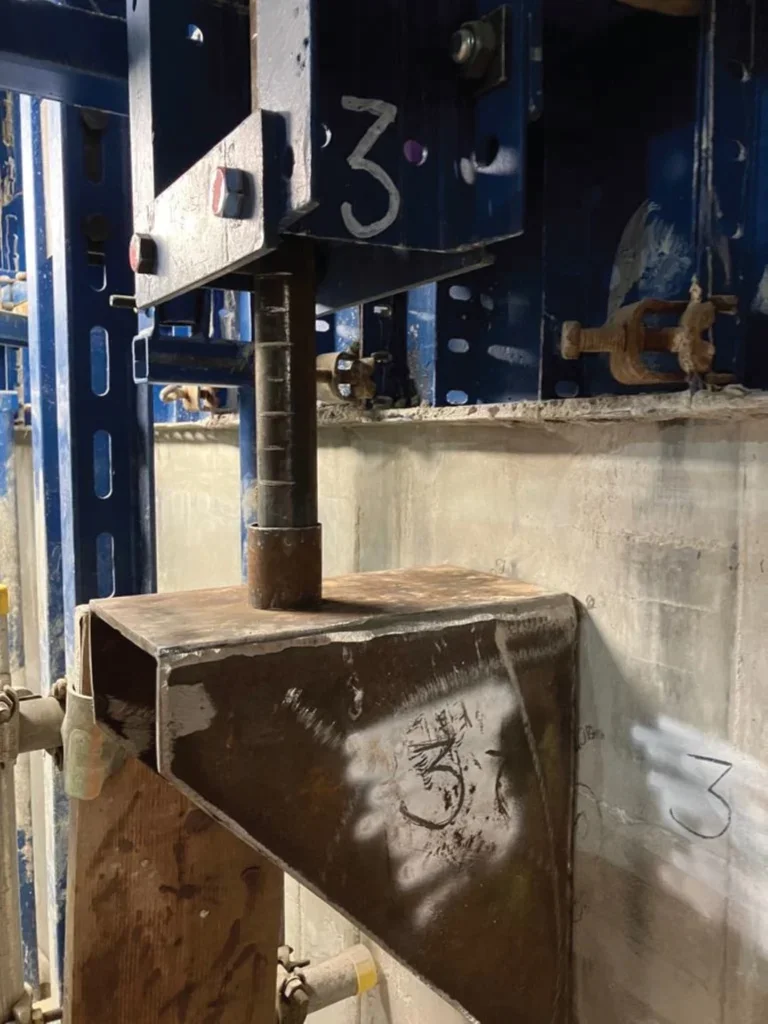
The relocated climbing tubes were supported on brackets fabricated on site. The process from initial concept to fabrication was accelerated to avoid delays to the slipforming operation. Fabrication was carried out during the night shift following advice from the slipform team, with the temporary works design finalised the following day. Once the design was confirmed, an additional gusset plate was welded onto the brackets, after which they were ready for installation. They were then fixed to the cast secondary lining.
Relocating the climbing tubes to reduce the cantilever length, combined with limiting the load placed on the widened deck section, resulted in the slipform rig moving back towards its intended design position. An alternative solution could have involved adding supplementary support beneath the cantilever to stiffen the structure and reduce deflection; however, this would have increased the overall rig weight.
The specified tolerance for the finished concrete lining was +25mm to 0mm, and I set out the lining at +10mm to remain within this range. I submitted the as-built survey data to the designer to confirm whether the lining could be accepted as constructed. Although the change in diameter exceeded the absolute tolerance of ±50mm stated in CESWI clause 11.8, when expressed as a percentage of the design diameter (80mm / 25,000mm = 0.32%), it remained below the permissible 1% threshold. On this basis, the designer accepted the secondary lining diameter as built. This is based on the worst-case scenario at level 75.4m ATD whereby the shutter had pulled-in by 32mm on one side, and 48mm on the other, totalling an 80mm reduction in diameter for the 25m-wide shaft. A schematic of this is shown on Figure 12.
3.3. Rig alterations
As the rig approached the final 5m of the slipform, planned stoppages were introduced to accommodate the increased lining thickness, which rose from 600mm to 1200mm and required additional steel reinforcement. Rig alterations were also undertaken to facilitate the installation of structural components for the cover slab and ventilation systems, as illustrated in Figure 13 and Figure 14.
This stage represented an exceptionally busy period and coincided with a time when I was the sole engineer on site. To manage the workload effectively, I set up two EDMs on the rig, enabling me to move between assisting the steel fixers and carpenters, ensuring that no gang was left without work. By anticipating requirements and marking out points during operative breaks, I successfully oversaw the correct installation of five box outs, four void formers, and multiple sections of couplers as well as alterations to the shutter pans.
At the conclusion of my shift pattern, I produced a clear diagram identifying the type and location of each cast-in item and marked these positions directly on the slipform deck. This ensured continuity across shifts and provided clarity for subsequent teams during this critical phase of construction.
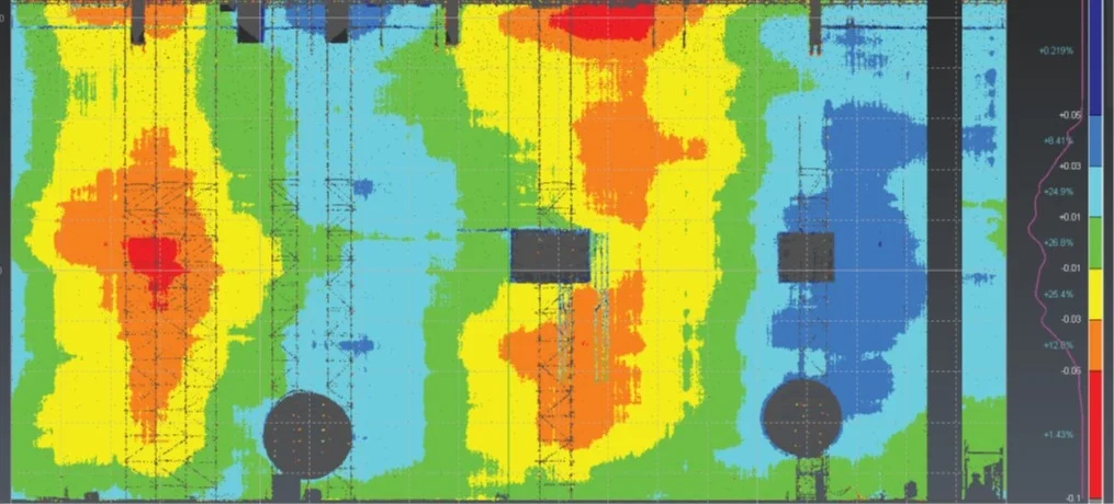
Following completion of the slipform, the rig was disassembled, and the concrete lining was scanned to assess the dimensional accuracy. The scan results, presented in Figure 15, illustrate the variation in lining thickness across the shaft. Areas highlighted in red indicate sections where the lining was 50mm thicker than the design specified, while blue areas denote sections 50mm thinner. Green areas correspond to the correct design thickness of 600mm.
In addition to thickness variation, the scan captured the locations of the various structures installed during slipforming which were created in preparation for the subsequent phase of works to complete the shaft internals. This survey provided a comprehensive record of the as-built condition and confirmed the lining was acceptable to use as constructed.
4. LESSONS LEARNT FOR THE NEXT SLIPFORM
Although the slipform operation was an overall success, several improvements could be implemented to enhance efficiency and outcomes in future projects. Greater preparatory work at the outset would have reduced stoppages during rig adaptations. Specifically, constructing the hanging deck at ground level would allow easier modifications, minimise work at height, and accelerate the process.
Boxouts at the top of the shaft should have been struck from the hanging deck while the rig was installed, rather than using a Mobile Elevating Work Platform (MEWP), which would have improved safety and productivity. Finally, the widened section of the rig, which proved vulnerable to deflections, could have been designed with additional support to stiffen the structure and maintain its shape throughout the slipform operation.
5. CONCLUSION
The slipform secondary lining works represented an exciting and rewarding project, from the initial site preparations through to the pouring of the final wagon of concrete. Extensive preparation prior to commencement ensured that the slipform process ran smoothly, resulting in a high-quality finish. This allowed the teams to dedicate more time to collaborative problem solving and ultimately delivered a watertight lining, ready to serve its operational purpose of diverting sewage flows from the River Thames, Figure 16.
By the end of 2025, the tunnel has successfully diverted and captured approximately 12 500 000 tonnes of sewage that would otherwise have entered the river. This volume is equivalent to around 5000 Olympic-sized swimming pools. Although no storm event has yet been large enough to fill the CARRR shaft, it is anticipated that the shaft will reach capacity up to five times per year.
6. ACKNOWLEDGEMENTS
I would like to extend my thanks to every member of the BMB JV team, and in particular to my shift team, whose commitment and cooperation made the site both an enjoyable and safe place to work. I am also grateful to the Client, Thames Tideway, and to the designers, MSES and Hewson Consulting, for their support and expertise.
The success of major construction projects relies on strong collaboration, and this was the primary factor behind the successful delivery of the slipform. I would further like to acknowledge all those who have supported me throughout my career and provided opportunities to contribute to challenging and rewarding projects.