


The June 2025 evening BTS talk described the design to date of the stations for Prague Metro Line D with special focus on the complex Nové Dvory station. The talk was presented by Petr Makasek, Head of Tunnel Department, Mott MacDonald Czech Republic, who has more than 20 years of experience delivering underground works across Europe and beyond. At the time of the talk he was Project Manager/Responsible Engineer for Line D’s Nové Dvory station.
The mined station at Nové Dvory is an unusually large station cavern, incorporating: steeply rising escalator connections; a mid-station dome to enable two-way excavation of the station cavern; and, a pair of turnout tunnels supported by reinforced concrete (RC) pillars for future line branching. The lecture drew on preliminary and detailed design phases, outlining sequencing, modelling and verification approaches, and commenting on programme and procurement realities in Prague.
1. INTRODUCTION
Prague’s metro opened in 1974. Early sections were shallow and built mainly by cut and cover, reflecting the system’s original conception as a light underground tram. Later sections were constructed as Soviet-style metros — which are wider than London Underground, with an internal diameter of 5.1m for the running tunnels.
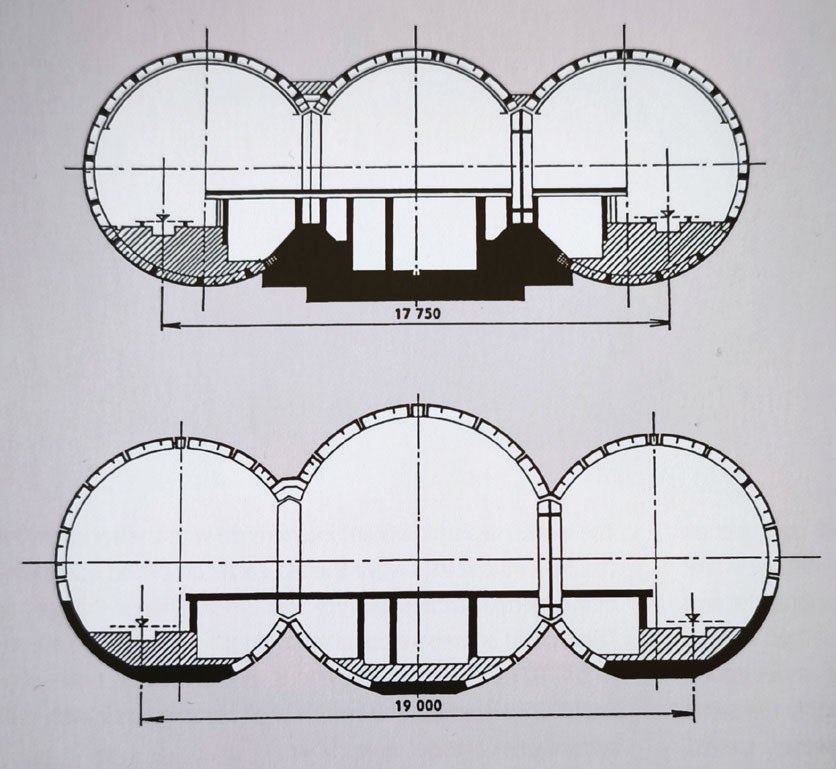
These were typically constructed using the ‘Prague Ring Method’, which consists of full face excavation with cast iron segmental linings installed by erector. The stations were usually three aisled mined stations constructed by a combination of cast iron linings together with RC pillars. In recent history, however, single cavern stations have been preferred on the Prague Metro, the first of which opened in 2004 as part of the Red Line extension.
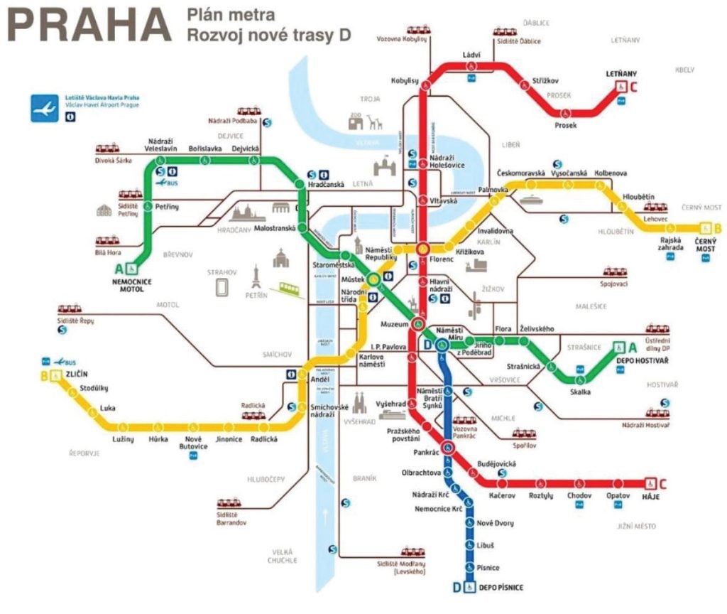
Today the network comprises three lines (A – Green; B – Yellow, and C– Red), totalling 65.4km and with 61 stations, carrying approximately one million passengers a day (2023: 338 million). The last metro line built — Line C — was opened in 2015 and since then the city has been waiting for the next line, Line D, to be built.
2. LINE D
Line D, which will be the fourth line for Prague, will be 10.6km-long with 10 stations connecting the city centre to the southern suburbs and with intersections with lines Green and Red. It is the first line to be designed for fully-automated, driverless operation.
For delivery, and bearing in mind the complex permitting process, the client has partitioned the works into the sub sections:
- _ Section 1a – under construction, and includes two stations;
- _ Section 1b – in tendering, and has three stations including Nové Dvory which is the subject of the talk.
- _ Section 2; and,
- _ Section 3.
The Line D project timeline has had a long gestation from initial concepts in 1983 through environmental and economic studies in the 1990s–2000s, zoning and building permits in the 2010s, and protracted permitting and procurement. Section 1a entered construction in 2022 after building permit award; Section 1b’s tender has remained under challenge since late 2022, with bidder objections, anti corruption reviews, and re awards extending the process.
Mott MacDonald is responsible for the Detailed Design of Section 1b.
3. NOVÉ DVORY STATION
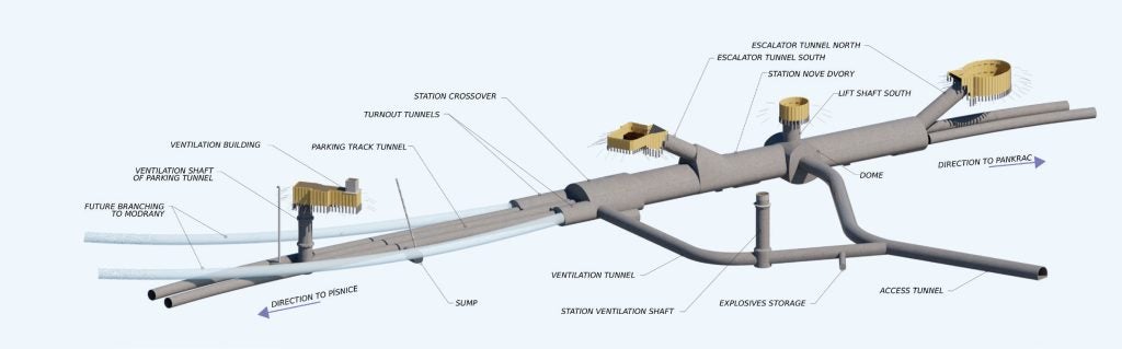
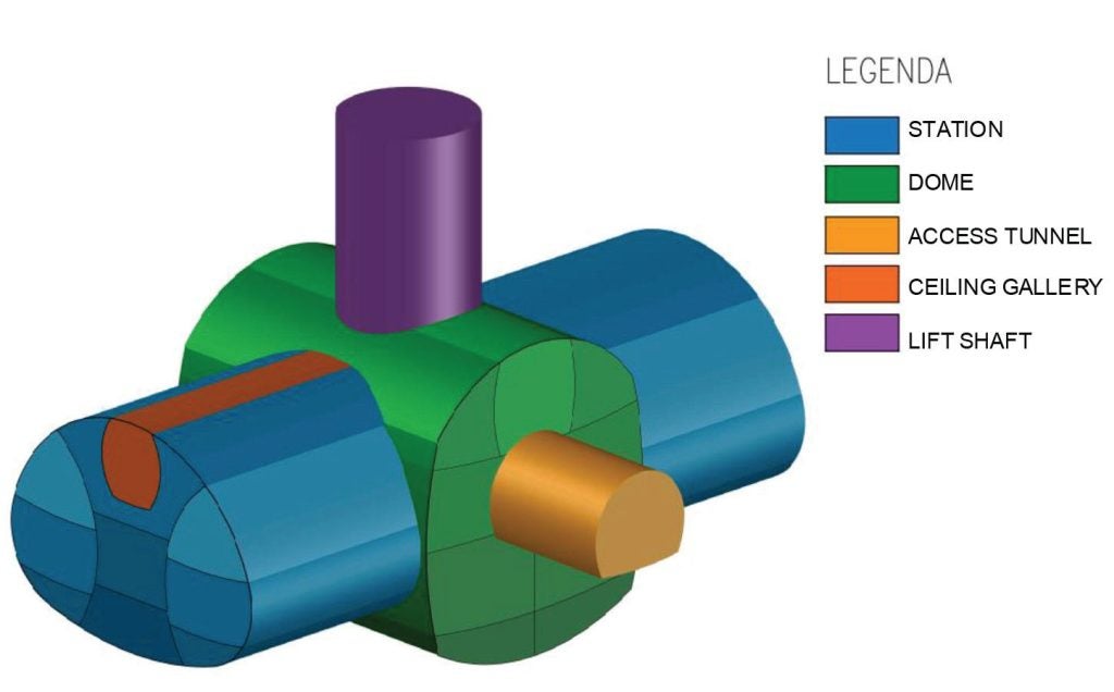
Due to the phasing of the project, Nové Dvory station will operate as a terminus for several years. The mined single cavern station sits within a cluster of structures: a construction access tunnel; a crossover; turnout tunnels provided for a future western branch; and, a parking track tunnel linked to another ventilation shaft.
The station platform will be 100m long and connect to the surface by a lift and two steep escalator tunnels, inclined to rise to the surface at about 60°.
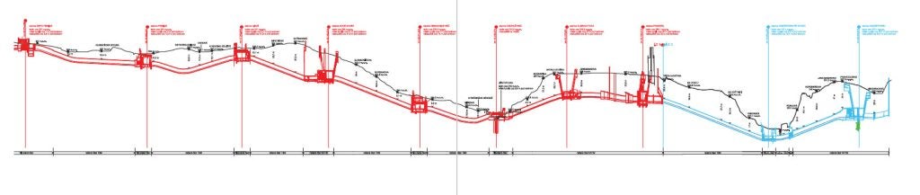
The site geology is dominated by clay-silty shales, and silty shales ranging from weathered to fresh. The longitudinal geological section indicates the presence of two formations separated by a fault towards the northern end of the station. Detailed ground conditions remain uncertain and therefore the fault area has been represented by a 3m-wide vertical band, which will be a key focus for observational control.
The station is to be fully waterproofed with the groundwater anticipated to stand at about 19m above the station crown.
4. EXCAVATION AND PRIMARY LINING
A key project milestone is to complete primary linings at Nové Dvory within two years to be able to accept TBMs driving in from the south. This has led to the multi-access approach of using shafts and escalators to start as many headings as feasible, in parallel. Five sites are anticipated to be excavated at the same time.
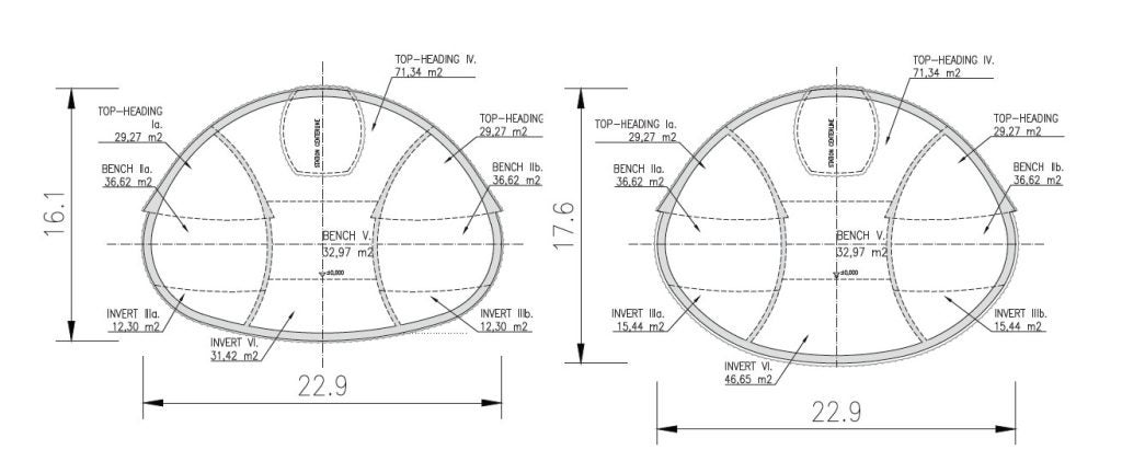
Typical cross section of the station is 22.9m-wide and 16.1m-high, rising to a height of 17.9m at the junction with the escalator tunnels. The design employs the New Austrian Tunnelling Method (NATM) with staged excavation supported by sprayed concrete primary lining, rock bolts and spiles, with systematic monitoring for convergence and settlements.
Typical station sequencing uses excavation of the side‑wall galleries (in the sequence of top heading, bench then invert) followed by the central core (top heading, bench, invert). However, the geometry of Nové Dvory station requires tailored solutions at three critical areas: the mid‑station dome; the escalator tunnel south connection; and, the turnout tunnels with RC pillars.
4a. Mid-station dome
A large dome is introduced roughly mid‑station to create a logistics and access node that enables simultaneous excavation of the station cavern toward both ends. The dome is deep due to the need for accommodating the lift pit.
The excavation sequence is assumed as a complex arrangement of small chunks constructed as top heading/benches and invert excavation. The final opening is approximately 20m-wide by 22m-high with an area of approx 366m2. The primary lining is engineered from 3D-staged modelling in MIDAS GTS NX.
A false primary lining (perpendicular to dome) will later be built inside the dome as formwork for the station secondary lining casting. The space between the false primary lining and the dome will be filled with ash concrete, a lower carbon alternative to traditional concrete.
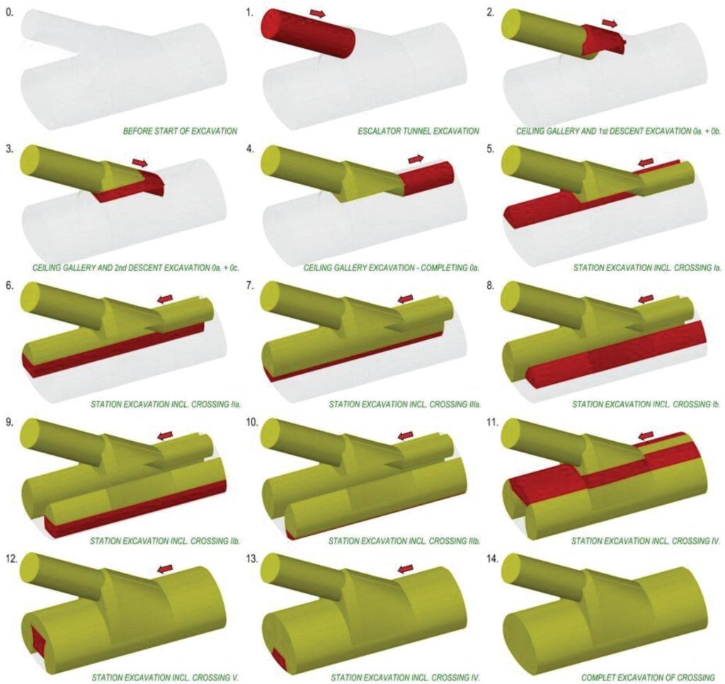
4b. Escalator Tunnel South Connection
Client requirements combined the station cavern and a steeply rising escalator tunnel in a single envelope that the designers dub the ‘egg’. The tunnel envelope flares laterally while climbing at circa 60°, creating a large and highly three‑dimensional intersection.
The construction sequence begins with a ceiling gallery from the escalator tunnel, then two descents to form the inclined connection before switching back to the station’s typical sequence.
The connection cavern reaches an area of approx 417m2 and it is 28.5m in height, which is roughly equivalent to a seven-storey building (3.5m per floor). Detailed 3D analysis of the overall construction sequence, in MIDAS GTS NX, was used to set the support required, evaluate displacements and optimise staging. The complex sequencing demands careful headwall anchoring and control of load paths into the side‑wall galleries.
4c. Turnout tunnels
Provision for a future western branch is realised with two large turnout tunnels to be located immediately beyond the station crossover. Where the rock pillar between diverging tubes becomes too thin, reinforced‑concrete pillars (constructed in a middle tunnel) replace rock capacity and provide support to the primary lining of the parking track tunnel and turnouts.
The complex construction sequence enlarges a ventilation tunnel in the crossover area, drives the middle tunnels, casts the RC pillars (approximately 5m-high and 1m-thick in the thinnest zone) and then executes a stepwise enlargement to the full turnout profiles using the support of RC pillars.
5. EXPECTED SETTLEMENT
The NATM design is underpinned by instrumentation— settlements, convergence and other response measures—with trigger limits set for each stage. Predicted maximum settlement above the Escalator Tunnel South, which is the biggest structure in the station, is around 105mm. During the ground movement assessment one building was flagged as critically affected and is therefore scheduled for demolition during the works. The impact on other surrounding properties has been assessed and is expected to remain within acceptable thresholds for settlement and damage.
6. STATION SECONDARY LINING
Secondary lining for the station is divided into seven construction sections (DP1-5). The overall construction programme for the secondary linings is determined by receiving two TBMs from the south.
When they are being pulled through the station the pours can proceed for the station sump and the parking track tunnel and its ventilation shaft. After the TBMs have been pulled farther through the station then casting be done for the turnout tunnels, ventilation tunnel and the station ventilation shafts. Once the machines have passed through to the end of the station then casting of the lift shaft, escalator tunnels and station internal RC structures can proceed.
The most challenging geometry for casting the linings is at the escalator‑station connection. Given the three‑dimensional geometry at the ‘egg’, a hybrid of form‑traveller and bespoke timbering is anticipated to be used, with the final construction methodology defined in the contractor’s design.
7. OVER SITE DEVELOPMENT (OSD)
The city of Prague will own the station and the land above it and has created a company for Over Site Development (OSD). The station design is currently being updated to integrate the vestibules within the OSD. The building foundations will be separate from the station, and the depth of below‑grade storeys has been limited to avoid overloading. It has been verified that OSD load effects sit within the station design envelope.
8. GEOTHERMAL ENERGY HARVESTING
As part of the project, the city is piloting geothermal energy harvesting. A ground source heat pump system consisting of 20mm collector loops will be fixed to the first reinforcement layer in the secondary lining, close to the interface between both linings. The loops will be connected via the South Escalator Tunnel to a heat pump at the basement level of the OSD. Preliminary estimates indicate potential annual supplies of the order of 1250MW to 1500MW per year for heating and 600MW-800MW per year for cooling.
9. OTHER SCOPE
Mott MacDonald is also responsible for the design of three other major structures within Section 1b, as follows: 9a. Nadrazi Krc Station Station Nadrazi Krc is an at grade station partially constructed on a bridge above a pond.
The station is divided into northern and southern sections, and a nearby stream will be diverted within a pile structure. The northern part has cross walls to enable the excavation to cross the city ring road in several phases. The southern section is designed to receive the TBM coming from the south. The walls are designed as a combination of pile walls, soldier pile walls and sheet pile walls.
9b. Nemocnice Krc Station Box
This station is a typical station box. It is dived into two phases to allow for the diversion of the highway during the construction. The box is constructed from secant pile walls with anchors provided at several levels. Some of the walls will act as foundations for future Over Site Development, with the design based on loading derived from initial studies for the buildings.
9c. Rezerva TBM Launch Shaft
The final part of Mott MacDonald’s scope is the shaft where the TBMs are launched on northward drives. The shaft is constructed using diaphragm walls (D-Walls) with flood protection barrier included, in case of flooding in the local area. The D-Walls are supported with a combination of ground anchors and props.
10. CONCLUSIONS
Nové Dvory is a large, complex mined station executed in competent shales with high groundwater levels, requiring robust NATM staging, 3D analysis and logistics‑led features such as the mid‑station dome. The escalator connection and turnout complex impose unusual geometries, but the design presents a clear sequence to control deformation and maintain programme in the lead‑up to TBM arrival.
The work illustrates how Prague’s heavy‑metro tradition is evolving toward expansive single‑cavern stations where geology permits—balancing architectural ambition with constructability and ground response.
Q&A
Following his presentation to the BTS meeting, Petr Makasek took questions from the audience.
Q: Matthew Hubble, Mace Dragados: Given the incredibly impressive scale of the tunnels, is this the most economical way to build them, or more of an architectural statement piece for the city?
A: Who knows? Maybe more architectural than understandable from the technical point of view. There is a preference for this one cavern system and because there is good rock it can be constructed. This is the result of many discussions with the client.
Q: Nick Lock, London Bridge Associates: Looking at the escalator shaft what is access for construction? Secondly, what is the programme for the complete construction?
A: The complete construction programme for the station is five years: two years for primary linings, and the rest for casting the secondary linings and internal structure. As two years is a short construction period the team will use all available access points (shafts, escalators) to launch headings in parallel. The ventilation shaft for the track is situated close to the problematic part at the turnout area, that’s the reason why we are going via the shaft.
Q: Hayden Davis, Retired (tunnel engineer): Are you assuming the successful contractor will use Drill & Blast? Has the vibration risk to nearby structures due to the blasting been considered?
A: Yes, blasting is expected in competent rock but is subject to environmental assessment constraints in the city. The effects of vibration on the surrounding buildings have been assessed; one building is scheduled for demolition during the works.
Q: Nick Chittenden, Independent: You have a huge amount of shotcrete works ongoing for the temporary works. What sort of volumes are you anticipating and have you looked at specifying any certification for the operators to ensure quality, efficiency and optimisation for the application?
A: Sprayed concrete is standard practice in the Czech Republic; contractors are certified, although industry‑wide shortages of skilled operatives are a concern. I do not remember the total volume.
Q: Mike McConnell, Retired (Balfour Beatty): Temporary works design will play a very central part in this, and I would be appreciative if you could elaborate on how the actual Contractor´s contract is linking in here. It would be good to have the temporary works design wholly under the Contractor´s brief, if that is possible. How is it to be designed and managed?
A: Designer will undertake temporary works design within an established division of responsibilities; contractors bring methodology and means in construction design.
Q: Ali Mahdi: Considering the high hydrostatic head, please elaborate on the approaches employed to ensure watertight and waterproofed connections and joints.
A: A combination of sheet membrane and spray‑applied systems is envisaged, with details to be finalised at the construction stage.
Q: I have made some correlations from our experience in Egypt and, regarding the previous question, sharp corners usually suffer from water ingress inside. How was numerical modelling validated? Do you specify monitoring during construction to ensure your design is safe? How will unsymmetrical lateral loading be handled as the station seems to be in areas fully congested but with zones that are vacant to one side (not loaded) and heavy loaded to the other side, considering you are designing for both short- and long-term?
A: Monitoring is part of the NATM method, so the monitoring design and instrumentation were considered and settlement limits set at all construction stages. Critical 3D staging was modelled in MIDAS; Plaxis was also used and secondary linings were checked in other tools (e.g., Revit). Several different software packages were used for validation. Designs were independently checked to validate the design.
Water ingress during primary lining construction is not expected as we are dewatering but secondary lining design has considered full water load.
Q: Was conventional rebar used or GFRP? What did you use for the diaphragm walls?
A: We used conventional steel reinforcement. Fibreglass reinforcement was used in the tunnel eyes for the future branch lines.
Follow-on Q: Is Prague a seismic zone?
A: No, we don’t have earthquakes.
Follow-on Q: What constitutive models were used in analysis of the lining and the surrounding soil?
A: Several were used, Mohr-Coulomb for soil, and Hoek-Brown for rock.
Q: Jen-Li Chu, Morgan Sindall: What is the impact of OSD pile foundations on the station?
A: The Over Site Development (OSD) was proposed following the completion of our design and this was an issue. The team limited the OSD basement depth and verified station–OSD interaction to keep effects within design allowances; certain initial proposals for deeper basements were rejected.
Follow-on Q: With hindsight knowing there would be an OSD would you have adopted a station box?
A: The building foundations will consist of retaining walls around the station. The secant pile walls around will not affect the station.


