

A recent paper from hydropower researchers proposes to use combinations of traditional open and closed large surge tank caverns in underground water tunnel systems to help achieve faster and better damping of the large-scale forces that quickly arise from dynamically changing flows.
In terms of tunnelling, the recommendation would suggest more complex underground configurations for hydro projects, and design and excavation of more caverns and shafts each time.
CHALLENGE
With more demands coming from electricity grids to hydropower plants, especially pumped storage systems, the power plants would have more oscillations of water masses in their tunnel systems, and sometimes briefly but powerfully. This would result in more hydraulic transients washing through the network of tunnels and requiring damping down.
The classic term for such combined pressure wave transients and mass oscillations is ‘water hammer’. Hydropower systems of all kinds are designed to minimise such effects and the ensuing dynamic forces. Often this is done by a variety of means, such as careful governing of flows through operation of hydraulic valves, guide vanes, blades and turbines. An additional facility, and clearly seen in tunnel layouts of hydropower plants, is to have large surge tanks that are, in effect, pressure relief valves. They help to brake the mass oscillations of water and pressure transients passing along tunnels by offering vastly larger local spaces to expand into and for the flows to churn, so helping to provide the necessary damping of the movement and energy.
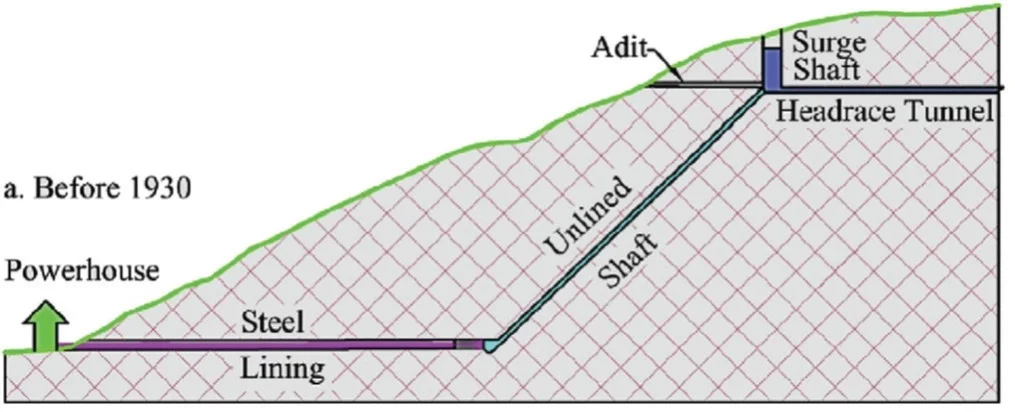
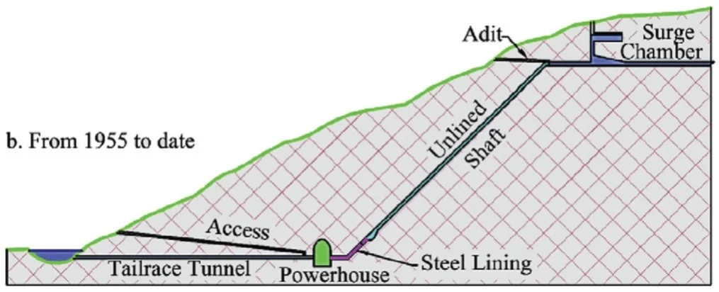
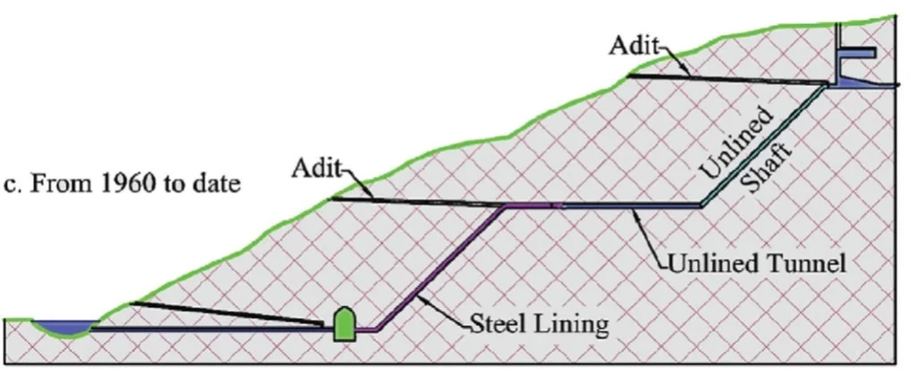
The surge tanks are large openings, connected to the principal tunnels, or headraces, in different ways. They are effectively caverns and in many older hydropower project designs, such as in Norway, they have vertical shafts; other orientations can see them as surge chambers, which are more used in projects in more recent decades, and long inclined shafts also are in play. Depending on the project, the hydraulic network can be designed as to have them located at different points, generally upstream of underground powerhouse but there can be an additional one downstream.
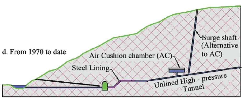
Some of these underground surge tanks are open (which respond slowly to mitigate the oscillations of water mass and transients), others are closed – sealed with a volume of pressurised air inside, above the water surface (and offer faster mitigation).
RESEARCH
With those baselines for all hydropower, and noting the potential for the energy generation type to offer more to support decarbonisation, flexibility of large-scale energy storage and electricity grid support in various ways, the researchers – based in Norway and Ethiopia – noted that there are adaptability limitations that need new considerations in surge tank design.
To address the challenge they considered a novel composite surge tank for use in hydropower systems with long headrace tunnels, using a 1.3GW pumped storage project in Norway to look at possibilities and options. The facility is the Gravatn pumped storage scheme, which will have large upper and lower reservoirs (Gravatn and Sirdalsvatn, in operation since 1973 and 1968, respectively).
The researchers analysed transients for selected load change scenarios for open, closed (air-cushioned) and composite surge tanks arrangements – which are configurations that combined both open and closed surge tank types into this novel whole-system approach. The load change scenarios were for load rejection behaviour (disengaging with power grid) of 25%, 50%, 75% and fully; and, power ramping to 5%, 10% and 20% load acceptance. Governor response and frequency support response were also modelled.
The simple open surge tank had the distance of 22.7km from the upper reservoir along the headrace to the tank, with static head of 245m; and, inclined tunnels and drop pressure shafts then lead to underground powerhouse, with a head difference of 465m.
For this design analysis, the closed surge tank was taken as located relatively near (approx 200m upstream of the pressure penstock that takes flow into the powerhouse); the closeness was to maximise the damping effect.
The combined surge system has an arrangement of these types to analyse.
In comparing the analyses, the researchers describe the combined surge system as demonstrating excellent performance across parameters, such as governing, mass oscillation damping, power ramping, and minimised pressure fluctuations. They said that this surge tank approach, in this analysis, for example damped the 40m water hammer and mass oscillation surges of the open and closed surge tanks into 8m in front of the turbine.
The analysis was offered to further inform the design development for the future of the Gravatn complex.
The researchers add that the findings shows the design can enhance potential for the upgrading and expansion of existing underground hydropower assets as well as encourage new such tunnel projects, and they advocate for implementation of the new surge tank design approach.
For tunnellers, this research points to potentially more and larger surge tanks being in the design and excavation of hydropower projects in hard rock, and with potential for such construction work on existing assets as well as new, even more complex major underground projects.
The full paper by Tesfay, A.H., Lia, L. & Vereide, K. was published in Elsevier’s ‘Renewable Energy’ journal, Volume 251, 1 October 2025, 123433, and is available at https://doi.org/10.1016/j.renene.2025.123433. The paper was published under a Creative Commons licence.
Clarification
The article ‘Creep versus consolidation in tunnelling through squeezing ground’, published in the December 2025 issue of Tunnels and Tunnelling International (pp. 10–20), was originally published as open-access in Rock Mechanics and Rock Engineering, as two complementary papers, Part A and Part B, and issued separately, each with full allowance by the authors (Georgios Anagnostou and co-authors) and the journal for adaptation to share knowledge. As permitted, T&TI developed an adaptation, bringing the papers to sit alongside each other, in shorter form. The authors clarify that they were not involved in the preparation of the synthesis section of the article, which was written by T&T and introduces the adapted papers; they are recognised as authors of the main parts of the article.
HYDRAULIC TRANSIENTS AND FLEXIBILITY
Hydropower systems involve water flowing, and changing direction, in networks of large-scale underground conduits. As such, there will be pressure waves generated, dynamically. These are pressure transients and need to be carefully designed for – and built for – to enable a tunnel complex to withstand the forces, and also be resilient over the long-term.
This challenge exists especially for pumped storage power plants, typically with more tunnel networks and by design reverses the flow to send the water mass back to where it started, in addition to the transients. The water mass effectively re-loads the system. Where, then, is the advantage?
Moving water to generate electricity creates sales and therefore money, whereas pumping the mass back uphill costs money: so long as more is earned moving each unit volume than costs to send it back, at cheaper times of grid power, then the difference, or spread, is where the business, and economic, advantage arises.
So long as the system keeps working effectively, or much
The challenge to keep working is becoming greater from additional demands coming from the power grids. Simply generating and slowly pumping back up was the traditional, perhaps old way. While still core to the pumped storage ethos, these power plants are now looked to operate more iteratively, briefly, quickly, all to provide rapid response support to the electricity grids.
The grids themselves are facing increased challenges and load demands, and service support, much arising from the requirement to take on the opportunities and burdens of fluctuating renewables (solar, wind). The rapid-response capability of hydropower – able to start generating within seconds, and the only key competitor to similarly ultra-fast responses of gas-fired power plants – also brings calls to help with grid stabilisation, in load and frequency maintenance, and this can be relatively brief and local. The result, for hydro plants providing such more complex services, is more hydraulic transients.
As demands on grids are expected to increase in these varied ways, the demands on – and opportunities for – hydropower are also rising, and the requirement for ensuring that transients are understood and managed effectively.


